Download
1 / 46
480 likes | 548 Views
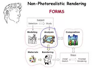
Explore various non-photorealistic rendering methods such as technical illustration, painterly rendering, and sketchy rendering to create expressive and artistic computer graphics. Learn about shape abstraction by lines, shading, textures, and edge detection techniques for effective rendering. Discover software and hardware methods for detecting silhouettes and creases and achieving charcoal effects and illustration examples in your graphics. Enhance your skills in line weight, color, and tone shading for more visually appealing renderings.

E N D
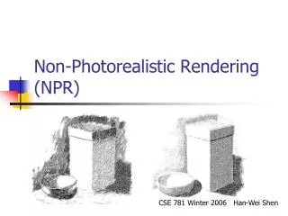
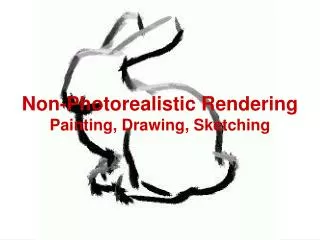
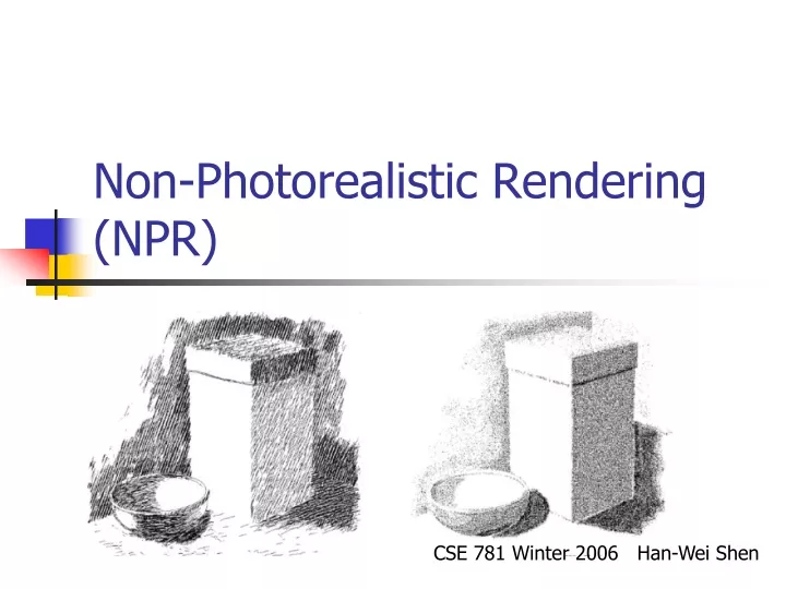
Non-Photorealistic Rendering (NPR) CSE 781 Winter 2006 Han-Wei Shen
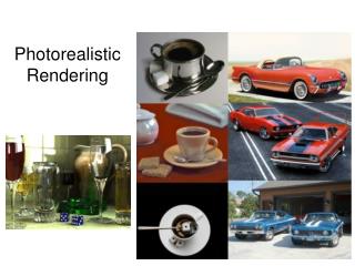
Non-photorealistic Rendering • Most computer graphics work strives for photorealism • Other types of depiction can be more expressive or artistic
NPR – Technical Illustration • Illustrate important features
NPR – Painterly Rendering • Make it look like being created using brush strokes and paint
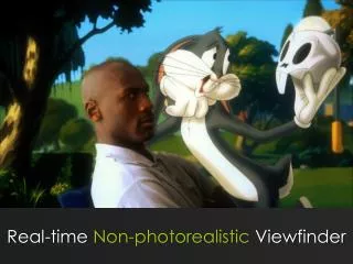
NPR – Sketchy Rendering • Make it look like being created with pencil sketch
Shape Abstraction by Lines • Boundary Lines • Silhouette Lines • Creases • Material Edges
Shape Abstractions by Lines • Various line styles can be used
Shape Abstraction by Shading Regular OpenGL Gouraud Shading Tone Shading
Shape Abstraction by Shading • More effective when combined with lines
Feature Line Detection • Image space method – analyze the rendered images • Object space method – analyze the mesh
Image Space Method • Analyze the depth buffer – look for depth discontinuity using edge detector
Image Space Method • Analyze the Normal Map – convert surface normal (x,y,z) to (R,G,B) and then detect the color discontinuity
Image Space Method • Better result can be obtained if both edges are combined
Edge Detector • Discontinuity in depth map or normal map can be detected using edge detector Ix(x,y) = I(x,y) x Sx; Iy(x,y) = I(x,y) x Sy IM = sqrt ( Ix(x,y) + Iy(x,y) ) Get edge by thresholding IM 2 2
Image Space Method Problem • For a folded piece of a paper, the edge cannot be detected
Object Space Method • Mainly used to detect silhouettes and creases • Silhouettes: edges that connect front and back faces • Creases: A discontinuity on an otherwise smooth edges
Silhouette • For a smooth surface, a silhouette can be defined as: • N. (X-E) = 0 ; N: normal, X: silhouette point; E: camera
Software Method • Detect Silhouettes from all triangle edges • For each vertex, evaluate: • d = n. (x-e) / |n|*|(x-e)| • s = + if d >0; else – • Find s = 0 along face edges
Hardware Method • Use OpenGL to draw silhouette edges (no explicit search) • Pseudo code (a three pass method) draw shaded front faces draw front faces in line mode, set stencil draw back faces in line mode where stencil was set; decrementing stencil
Hardware Method • Reduce to 2 pass by push the backface forward (z bias) visible backface Eye Angle dependent front back Use glPolygonOffset
Issues of the previous method • Non-uniform z resolution needs to be taken care of – translate by k*z; • K: a scaling factor, z: the polygon distance • The width of the line will depend on the orientation of the back-facing polygon and front-facing polygon • Raskar and Cohen – fatten the back-facing polygons
Raskar and Cohen’s fix • The back-facing polygon edge is pushed outwards By Offset = K * z/V.Nb Nb v F B B F The distance to push only depends on the orientation of back-facing polygon
Raskar and Cohen’s fix • In fact, each of the polygon edges needs to be pushed by a different amount: z*sin(a)/V.Nb; where cos(a) = v.e, e is the polygon edge vector
Charcoal Effect • Tessellate the polygon to smaller pieces • Also fatten front-facing polygons with 0<N.V<0.1 • Assign color I = (1+V.N)/3
Line Weight • Some possible choices: • Single line weight used throughout the image • Two line weights, with heavier describing the outer edges (boundary and silhouette) • Various light weight along a single line, emphasizing perspective effect (heavy lines in the foreground, tapering toward the farther part of the object)
Line Color • Attempt to incorporate shading • Interior lines can be drawn in white, simulating highlight
Tone Shading • The standard Phong Shading model is not always satisfactory • Problems in regions where • N.L < 0 • Only Ambient Colors are seen • Difficult to deduce shapes • Object outlines cannot be seen
Two ad hoc solutions • Hand-tuned ambient color • Just highlights and edge lines Ambient is only a constant Not enough surface detail
Effective Shading Model Needed • Shading Model is insufficient • Lost shape information • Especially in the areas of subtle curvature (small claws above) • Not automatic, lots of hand-tuning
Tone Shading Goals • To include shading in an image with back edge lines and white highlights visible • Use a compressed dynamic range for shading • Use color visually distinct from black and white
Reduce dynamic range • One way to compress dynamic color range is to use colors of different tones • Add gray to a color to generate different tones Unnatural color Lack of luminance difference
Create Undertone • To further differentiate different surface orientations, we can use cool to warm color undertones • Cool colors – blue, violet, green • Warm colors – red, orange, yellow warm cold
Test Your Perception Which color (yellow or blue) seems closer?
Test Your Perception What about now?
Blend Tone and Undertone • Add warm-to-cool undertone to a red object
Use warm-to-cool undertone • We can modify the diffuse Phong Lighting Model (Blend cool and warm color ) I = (1 + L.N)/2 * Kcool +(1- (1+L.N/2)) * Kwarm The Light vector should be place in perpendicular to the gaze direction (usually place at up and to the right) Normalize N.L
Tone Shading Equation • Kcool = Kblue + aKd (undertone and tone) • Kwarm = Kyellow + b Kd (undertone and tone) Kblue = (0,0,b) b in [0,1] Kyellow = (g,g,0) g in [0,1] a and b are user-specified parameters Kd is the object diffuse color
Tone Shading Results b = 0:55, g = 0:3, a = 0:25, b = 0:5