Download

1 / 24
380 likes | 916 Views
Baluns And Ferrites*. * Not to be confused with Ferrets which are small, furry animals and not suitable for antenna construction. BALUN = BAL anced to Un balanced It’s a transformer used to feed a balanced load, i.e.: a dipole with an unbalanced line, i.e.: coax.

E N D
Baluns And Ferrites* * Not to be confused with Ferrets which are small, furry animals and not suitable for antenna construction.
BALUN = BALancedto Unbalanced It’s a transformer used to feed a balanced load, i.e.: a dipole with an unbalanced line, i.e.: coax. • Decreases feeder radiation by evening out the voltage and therefore balancing the current in each leg of the antenna. • The feed line becomes more independent of the antenna. We can change the coax length or move it around with less SWR change and in a perfectly balanced case no SWR change.
With a balun, radiation picked up by the feeder from each side of the dipole is equal in magnitude and therefore cancels at the feeder. This decreases feedline reflected current. The feedline becomes ”floating” and becomes more independent of the antenna.
The feedline should run away from the dipole at a right angle. The dipole should be parallel to the ground. A non symetrical antenna i.e.: Windom, OCFD .... will require the use of a current balun.
Types of Baluns Voltage • Transformer With Windings Providing A Balanced Output • In/Out Impedances Are Determined By The Square of the Turns Ratio. A Wide Range Of Ratios Is Possible. • Operates Over A Somewhat Limited Bandwidth (100 : 1). Current • Uses Transmission Lines Wound On A Core. • May Use A Coaxial Cable Or A Parallel Wire Line With Or Without Ferrites. • Common Impedance Ratios: 1:1 And 4:1. • Operate Over A Much Wider Band Of Frequencies.
1:1 Voltage Balun 3 Identical Windings • Generally 50:50 Ω. We should have ~ the same impedance at the input and output.
4:1 Voltage Balun 2 Identical Windings connected in series Terminate with 200Ω resistor to check SWR The measured inductance at the output is ~ 4X the input inductance as a result of inductance coupling.
Testing A Balun With An SWR Analyzer This test verifies: • Winding inductance • Winding distributed capacitance Voltage Balun Load Resistance* • 50Ω – 1:1 Balun • 200Ω – 4:1 Balun 50Ω Coax The minimum SWR should be below 1.5 In the middle of the balun’s frequency range indicating low losses. * Keep connections as short as possible
Open Circuit Tests With An SWR Analyzer 50Ω Load Coax Tee Voltage Balun Open Circuit 50Ω Coax The minimum SWR should be below 1.1 In the middle of the balun’s frequency range indicating low losses.
Current Baluns Pop Quiz! How many independent conductors, at RF frequencies, does a coaxial cable have? • 1 • 2 • 3 • 4
Current Baluns Pop Quiz! How many independent conductors, at RF frequencies, does a coaxial cable have? • 1 • 2 • 3 • 4 There are 3 independent conductors: • The outer surface of the shield • The inner surface of the shield • The center conductor
Current Baluns • The RF current that flows on the outer surface of the shield is independent of the inner shield current. This is so because at RF frequencies, the current penetrates very little inside the conductors. This is called SKIN EFFECT. • The SWR only applies to the inner shield currents (and center conductor). • The SWR is independent of the outer shield currents.
Shielded Load With a shielded load, the current stays inside the coax. • There is no current on the outside of the coax. • Adding ferrites on the outside of the coax has NO effect. This is how some Dummy Loads are Constructed. Shielded Load Coaxial Cable
Unshielded Load A dipole is an unshielded load. The imbalance in current, due to a non-resonant condition, causes current to flow on the outside of the coax shield. D i p o l e Coaxial Cable
Unshielded Load Adding a ferrite core adds resistance on the OUTSIDE of the coax shield. • The ferrite core has NO effect on the internal coax currents. • The ferrite core reduces the outside shield current. D i p o l e Coaxial Cable Ferrite Core
Current Baluns Ferrite Cores Antenna Coaxial Cable Equivalent Circuit at RF Frequencies The impedance of the ferrites should be high ( > 1000 ohms)for a well balanced output.
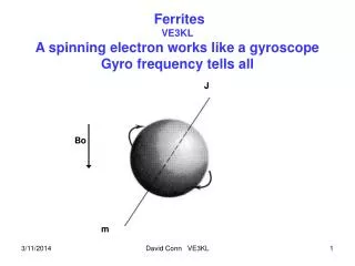
Ferrite Impedance Depends On • Material • Length • Volume of material • Varies with frequency To calculate the impedance z: (approx.) Impedance of One Turn for One Ferrite x Number of Ferrites x Number of Turns Squared NOTE: One Turn = Ferrite on a straight wire
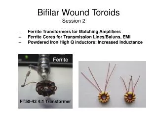
Ferrite Impedance Ferrites Vs Iron Powder Two Different Materials Ferrite • Has a High Permeability (10 to 15000). • High Inductance for a Small Number of Turns. • Inductance Obtained is not Stable and Q Factor is low. • OK for Transformers and Baluns. Iron Powder • Lower Permeability. • Lower Inductance. • Gives a stable, high Q inductance (I.e.: Vfo, Filters, Tuners).
Current Balun Made Up Of Coax Cable Dipole Coil Diameter 6-12” 5-10 Turns Effectiveness increases with the square of the number of turns.
Using A Balun On A Vertical Antenna Do NOT connect to earth ground here if only a few radials are used. Ferrites The coax should not be part of the antenna! Earth ground is OK here.
Using Ferrites On The Feeder Of Vertical Yagi ~ wl\2 #43 Ferrites Non-Metallic Mast
Summary Voltage Baluns • Cover a Very Wide Range of Impedances. • Set Equal Voltages at the Output. • Generally Provide NO Protection against Currents Flowing on Coax Shield Exterior. • May Be Combined With A Current Balun. Current Baluns • Create An Impedance On The Outside Of The Coax (OR Any Conductor). • Also Called Common Mode Chokes. • Decrease Coax Radiation And Pick-Up. • Stabilize The Antenna Impedance. • Generally 50:50 Ohms Ratio (ALSO 50:200 Possible). • Decrease Coax Radiation On Transmit And Pick-Up On Receive.