Download
1 / 8
80 likes | 98 Views
A comprehensive guidebook for the installation and assembly sequence of steel purlins, columns, and brackets in solar power plants. Includes step-by-step procedures, torque charts, and safety guidelines.

E N D
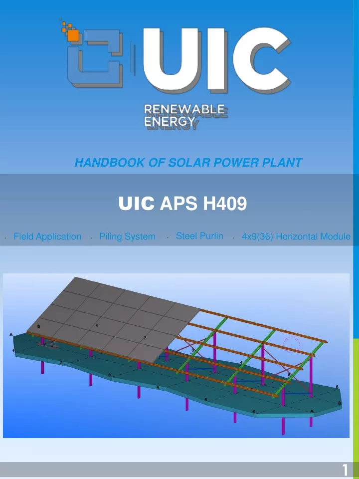
HANDBOOK OF SOLAR POWER PLANT UIC APS H409 • Steel Purlin • Field Application • Piling System • 4x9(36) Horizontal Module 1
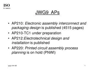
UIC APS H409 Material List No PARTS CODE DESCRIPTIONS TOTAL QTY (Pcs) LENGTH (mm) 1 KL 1 SHORT COLUMN 6 2 KL 2 TALL COLUMN 6 3 KR BEAM 6 4 AS PURLIN 5 5 PY BRACKET - 6 DC CROSS BEAM 6 7 ASK PURLIN CONNECTOR 30 8 MID MID CLAMP 54 9 END END CLAMP 36 10 CSP BOLT +NUT + WASHER - 11 12 13 14 15 2
UIC APS H409 Assembly Sequence Piling Montage 3
UIC APS H409 Assembly Sequence . PV Module Montage 4
Assembly Procedure Piling • Locate coordinates of each string’s start and end points. • Stretch a string between two posts. • Measure and mark on the string each column’s position with a tape. • Place a mark on column which indicates the level should be on string line. • Check the project and make sure the direction of C profile is whether facing to east or west. • Pile every column by paying attention of its verticality and stop piling when the mark is at the level of string. . Mounting Steel Components • Place the beams and put bolts, nuts and washers in position as shown in project. • Fasten bolts with hand. • Complete putting parts in place by sequence of; beams-brackets-purlins-cross beams. • Measure diagonal dimensions of plane of purlins where modules going to be placed. Make sure that it is exactly rectangular. • Fasten bolts by using torque wrench . Apply torques shown in the torque chart below. • Avoid using wrong size and uncoated items. 4
Assembly Procedure PV Module Installation • Put all aluminium clamps in place and tack bolts by hand. • Start putting PV modules at the lower corner of desk. And do it same with several desks same time before start putting the rest of the PV modules. • Use string to see straightness through east-west direction. • Put PV modules inside of clamps and make sure they fit inside well and no blank space between module and clamp. • Fasten bolts precisely according to torque chart below. . 4
Assembly Procedure Bolts Torque Chart . 4
BGS APS H410 03186 M.KYIV BULVAR JOKOLOIVSKII BUDINOK:19 KYIV /UKRAINE www.uicrenewable.com 5