Download
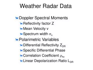
1 / 100
1.04k likes | 1.11k Views
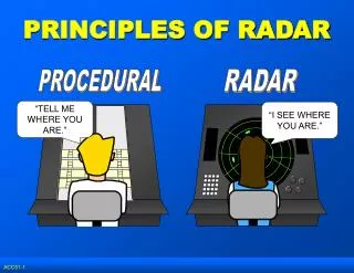
BASIC PRINCIPLES OF WEATHER RADAR. RADAR. Introduction to Radar Basic Operating Principles Reflectivity Products Doppler Principles Velocity Products Non-Meteorological Targets Summary. RADAR. RA dio D etection A nd R anging Developed during WWII for detecting enemy aircraft

E N D
RADAR • Introduction to Radar • Basic Operating Principles • Reflectivity Products • Doppler Principles • Velocity Products • Non-Meteorological Targets • Summary
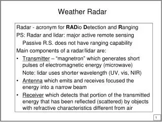
RADAR • RAdio Detection And Ranging • Developed during WWII for detecting enemy aircraft • Active remote sensor • Transmits and receives pulses of E-M radiation • Satellite is passive sensor (receives only) • Numerous applications • Detection/analysis of meteorological phenomena • Defence • Law Enforcement
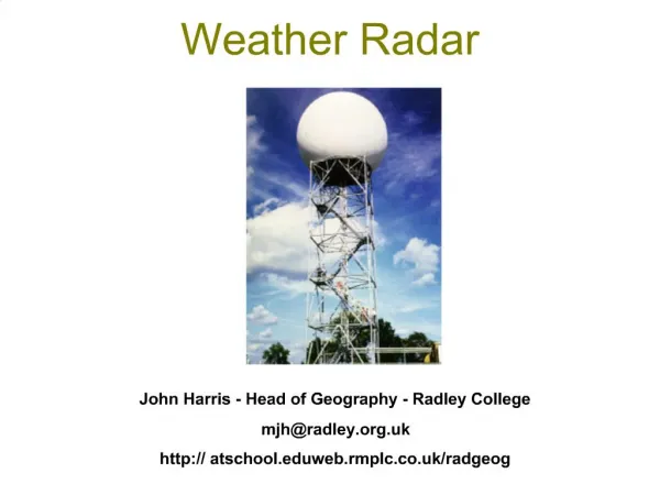
WEATHER SURVEILLANCE RADAR • Transmits very short pulses of radiation • Pencil beam (narrow cone) expands outward • Pulse duration ~ 1 μs (7 seconds per hour) • High transmitted power (~1 megawatt) • ‘Listens’ for returned energy (‘echoes’) • Listening time ~ 1 ms (59:53 per hour) • Very weak returns (~10-10 watt) • Transmitted energy is scattered by objects on ground and in atmosphere • Precipitation, terrain, buildings, insects, birds, etc. • Fraction of this scattered energy goes back to radar
BEAM RESOLUTION (http://www.crh.noaa.gov/mkx/radar/part1/slide3.html)
DETERMINING TARGET LOCATION • Three pieces of information • Azimuth angle • Elevation angle • Distance to target • From these data radar can determine exact target location
AZIMUTH ANGLE • Angle of ‘beam’ with respect to north
ELEVATION ANGLE • Angle of ‘beam’ with respect to ground (University of Illinois WW2010 Project)
DISTANCE TO TARGET • D = cT/2 • T pulse’s round trip time (University of Illinois WW2010 Project)
SCANNING STRATEGIES 1 • Plan Position Indicator (PPI) • Elevation angle constant, varying azimuth angle • Antenna rotates through 360° sweep at constant elevation angle • Allows detection / intensity determination of precipitation within given radius from radar • Most commonly seen by general public
PLAN POSITION INDICATOR • Constant elevation angle • Azimuth angle varies (antenna rotates) (University of Illinois WW2010 Project)
ELEVATION ANGLE CONSIDERATIONS • Radar usually aimed above horizon • minimizes ground clutter • not perfect • Beam gains altitude as it travels away from radar • Radar cannot ‘see’ directly overhead • ‘cone of silence’ • appears as ring of minimal/non-returns around radar, esp. with widespread precipitation • Sample volume increases as beam travels away from radar
Red numbers are elevation angles • Note how beam (generally) expands with increasing distance from radar (http://weather.noaa.gov/radar/radinfo/radinfo.html)
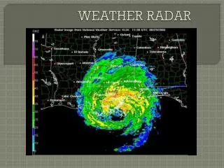
PLAN POSITION INDICATOR (PPI) • Plan position Indicator (PPI) display presents a plan view of echoes received in polar coordinate (Range (R), Azimuth ( ), Elevation ( )) system. • PPI is intensity modulated (i.e.) intensity of the echo depends on the strength of the signal received by the receiver of the radar
PLAN POSITION INDICATOR (PPI) • PPI display will have range markers ( at concentric circles) and topographical underlay so that a visual picture of weather echoes around the radar site can be easily appreciated by the user • It helps to identify the target (both in range and direction from the radar) precisely and hence is quite useful to locate the weather systems, centre of the weather system • With the modern digital radars, the intensity of the signal (echoes) can be displayed in suitable colour schemes for a quick interpretation of the prevailing weather
PPI display • Weather echo • Azimuth from • true north • Range (km) • A typical analogue radar PPI display will look like this, except that the colour of the echo is usually white. • But in digital radars, PPI, in addition to the above, displays detailed information about the scan, colours as well. • Range marker • Range marker • Range marker
PLAN POSITION INDICATOR (PPI) • Due to the earth’s curvature effect, the height of the scanning beam increases with the range. • Even for a small elevation such as 0.2o, the height of the radar beam will be at a height of about 3.0 km at 200 km range and 10.8 km at 400 km (after applying corrections for earth’s curvature) whereas it is hardly 0.3 km at 50 km and 0.9 km at 100 km • 0.3 km • 0.9 km • 3.0 km • 10.8 km • 50 km • 100 km • 200 km • 400 km
EARTH’S CURVATURE EFFECT • Assuming that Cb clouds of 12 km vertical extent are present at 100, 200, 300, 400, 500 km range from a radar, the bottom and middle portion of the Cb clouds upto a range of 300 km and only the top portion at 400 km are intercepted by the radar beam of 0.2o elevation. Cb cloud of 12 km height at 500 km range can NOT be probed at 0.2oelevation due to the earth’s curvature effect. • 0.2o beam do not intercept Cb of 12km height at 500km range
PLAN POSITION INDICATOR (PPI) • Interpretation of PPI may have to be done taking care that the height of the echo is NOT constant for all ranges for a particular elevation; instead the height of the target is higher at farther ranges and smaller at shorter ranges for the same elevation angle.
PLAN POSITION INDICATOR (PPI) • If the elevations are in steps of the beam width of the radar, then the PPI displays at different elevation angles give a total picture of the three dimensional overview of the weather system that has been probed by the radar • However, if there is wide gap between two adjacent elevation angles, then there could be wide gap in data between those two elevations and information on the exact weather system can not be clearly known.
PPI(Z).. 0.2oelevation • Pptn Echo File header indicating year, month, date, time (in UTC) and Product type, scan range • Precipitation echo
PPI(Z).. 0.2o elevation • Colour bar code to indicate the intensity of the echoes • Higher the intensity (dBZ), higher rate at which it is precipitating. • dBZ > 20 ordinarily precipitates provided such an echo is from weather clouds. • AZ : Azimuth • EL : Elevation : 0.2 deg
PPI(Z).. 0.2o elevation • Scan Range : 250 km • Scan resolution :0.5 km • Display Range : 250 km • Display resolution :1.25 km • Sea clutters (identified from the smudge shaped & wave pattern echoes) • Hardware parameters • CC : Clutter Filter • SQI : Signal Quality • Index • CSR : Clutter to Signal Ratio • Log : Log threshold • PW : Pulse width, Short = 1 s • PRF : Pulse Repetition Frequency • (Single PRF 600 Hz is used here) • AS : Antenna Scan rate, 9 deg/s • TS : Time sampling; • RS : Range Sampling
PPI(Z).. 1.0O ELEVATION • Sea clutters appearing at 0.2 and 1.0o elevations. • Note : Sea clutters could not be filtered by the clutter filter chosen in this scan • Note : Sea clutters could not be filtered by the clutter filter chosen in this scan as their velocity (in the range 1- 5 m/s) was more than the notch width of the chosen clutter filter (viz., 1 m/s).
PPI(Z).. 2.0O ELEVATION • Note that the weather echoes over land are still seen while the sea clutters vanished at 2.0 elevation anomalous propagation (AP) is confined to the low level and that too only over ocean.
DOPPLER EFFECT • Based on frequency changes associated with moving objects • E-M energy scattered by hydrometeors moving toward/away from radar cause frequency change • Frequency of return signal compared to transmitted signal frequency radial velocity
RADIAL VELOCITY • Hydrometeors moving toward/away from radar • Positive values targets moving away from radar • Negative values targets moving toward radar • Can be used to ascertain large-scale and small-scale flows/phenomena • fronts and other boundaries • mesoscale circulations • microbursts
PLAN POSITION INDICATOR (RADIAL VELOCITY) • PPI (V) : IT GIVES THE RADIAL VELOCITY ON A PPI SCOPE. THE RADIAL VELOCITY TOWARDS RADAR SITE IS TAKEN AS –VE AND AWAY FROM RADAR SITE IS TAKEN AS +VE.
PPI(V).. 0.2O ELEVATION • Warm colours (Red & Yellow) indicate that the hydrometeors are moving away from the radar • Radial velocity over land are due to hydrometeors within the clouds • Over the east and southern parts of Bay of Bengal, radial velocity of 1 to 5 mps (as high as 9-11 mps are also seen in the east) are due to sea clutters. • Cool colours (blue and green) indicate that the hydrometeors are moving towards the radar
PPI(V).. 1.0O ELEVATION • Weather echoes over the land (west to south) appear to move away from the radar. • However, over Bay of Bengal, the radial velocity of 1 to 5 mps are due to the sea clutters. • Note that the sea clutters seen at 200 – 250 km range at 0.2o elevation in the east has just diminished / vanished at this (1o ) elevation.
PPI(V).. 2.0O ELEVATION • Radial velocity due to medium / high clouds ( < 10 dBZ) in the northeast around 150 km range. • Radial velocity over land are due to weather echoes while the sea clutters in Bay of Bengal has just ceased.
SPECTRUM WIDTH • THE SIGNAL WHICH IS BACK-SCATTERED BY AN ASSEMBLAGE OF MOVING TARGETS CONTAINS INFORMATION ABOUT THEIR RADAR CROSS-SECTION AND RADIAL VELOCITIES. • BY MEANS OF A SUITABLE DATA-PROCESSING SCHEME, IT IS POSSIBLE TO EXTRACT THE BACK-SCATTERED POWER AS A FUNCTION OF DOPPLER SHIFT FREQUENCY. SUCH A FUNCTION IS CALLED DOPPLER SPECTRUM.
PLAN POSITION INDICATOR (SPECTRUM WIDTH) • PPI (W) : IT IS A MEASURE OF TURBULENCE AND IT IS OF IMMENSE USE IN NOWCASTING THE OCCURRENCE OF MICROBURST, WIND SHEER • LOW VALUE OF SPECTRUM WIDTH SHOWS UNIFORM WIND FLOW AND HIGH VALUE OF SPECTRUM WIDTH SHOWS TURBULENCE. • A TYPICAL PPI (W) IS SHOWN.
PPI(W).. 0.2O ELEVATION • Spectrum width is a measure of turbulence and gives an indication about the movement of hydrometeors within the sample volume. • W > 4.8 mps is indicative of moderate to severe turbulence. • Very minimum spectrum width (<0.8mps) over Bay of Bengal are indicative of sea clutters. • Higher spectrum width over land is due to the precipitating clouds. Large W > 3 mps from the sea clutters of large radial velocity.
PPI(W).. 1.0O ELEVATION • However, W in the sea clutters are very small in the range 0.1-0.8mps. • Sea clutters have typical shape.. orientation towards radar .. Smudgy …stretched lengthwise bit with minimum width • W in the precipitating and non-precipitating clouds are more over land
SCANNING STRATEGIES 2 RANGE HEIGHT INDICTOR (RHI) • When the antenna of a weather radar scans in a particular azimuth with varying elevations (i.e) known as elevation scan, RHI display is used • This display gives information about the height vis-à-vis range of the echoes, keeping the radar as the origin • Like PPI, this scope is also intensity modulated
RHI • Range Height Indicator (RHI) • Azimuth angle constant • Elevation angle varies (horizon to near zenith) • Cross-sectional view of structure of specific storm (University of Illinois WW2010 Project)
RANGE HEIGHT INDICTOR (RHI) • Continuity between two adjacent elevations has to be maintained so that the weather system can be probed without any data gap in between • Here again the curvature effect of the earth plays a significant role in interpretation of the echoes • For a given elevation, the lowest height of the echo at farther ranges will be at a higher height from the ground than that at the nearby range
RHI DISPLAY • A typical analogue radar RHI display will look like this, except that the echo will be in different shades of white / brightness. • But in digital radars, in addition to the above, RHI will have scan details, colour bar code as well. Precipitating echoes
RHI (Z) At farther range, the lowest height of the echo intercepted by the radar beam is higher than that at the nearer ranges. EL :Elevation 0 to 25 deg AZ : Azimuth of the elevation scan