Download

1 / 15
150 likes | 309 Views
Update on MPPC f rontend electronics development at IU. Gerard Visser. The setup. blue LED. The preamp. It is AC coupled here for prototyping convenience, but the real board will be DC coupled and feed each MPPC with an independent bias supply, as previously discussed.

E N D
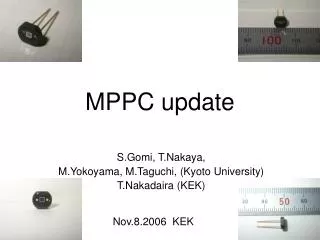
Update on MPPC frontend electronics development at IU Gerard Visser
The setup blue LED
The preamp It is AC coupled here for prototyping convenience, but the real board will be DC coupled and feed each MPPC with an independent bias supply, as previously discussed. Real board will include series damping resistor for each MPPC (probably use zero-Ohm jumpers).
Ganged vs. single MPPC Ref1: One MPPC, at nominal voltage, signal current 98 nA (2200 pixel) @ 1 kHz rate, dark current 223 nA Ch1: Two MPPC ganged w/o resistors, same voltage, ~same LED drive, not equally illuminated, signal current 179 nA, dark current 440 nA 720 mV/div 720 mV/div Ref1: as above Ch1: Four MPPC ganged w/o resistors, same voltage, not equally illuminated, LED drive adjusted for same signal current 98 nA, dark current 849 nA “No problem!” 720 mV/div 720 mV/div
Resolution with ganged MPPC Four ganged MPPC Same signal as above, 98 nA (98 pC × 1 kHz) This should correspond to ~2200 pixels ( 98 pC / (2.75×10⁵×q / pixel) ) Expect statistical noise 1/sqrt(2200) = 2.13% And that is just about what we get, only a little more. (Probably some excess noise factor for MPPC?? And of course some electronics noise.) 2.52 %
Pulse shape; single-pixel for calibration Four ganged MPPC (as above) This figure illustrates the pulse and its integral with a 65 ns integration gate such as may be used for e-RHIC (10 ns reset, 75 ns period). Speed is quite adequate and there is some margin to apply further pulse shaping if it proves useful. Four ganged MPPC (as above, no changes to the setup except adding −20× preamplifier to scope). Scope is set to 20 MHz BWL to provide a primitive shaping of the pulse. Few-pixel peaks can be observed, probably well enough for calibration. It ought to get better with adjustment of MPPC bias voltages and with better shaping/readout. Naively estimate 1 pixel ~410 μV, expected 0.73†×1.232 V / 2200 = 408 μV. Still, a more sophisticated fitting approach is probably needed to put the calibration on sound basis. †This accounts for 20MHz BWL peak gain.
Linearity & signal range Nonlinearity <<1% This is based on signal current and so on pixels fired, not incoming photon count, so does not include MPPC pixel-firing nonlinearity. But that part is out of my hands anyway The preamp load capacitor will be increased slightly to bring the linear range up to ~6000 pixels @ nominal gain. y=ax
Resolution As previously noted, there seems to be a small amount of ‘excess noise’ in the MPPC signal. I suppose this is expected? Based on the trend here, it seems not to be just the additive noise of the electronics. It could certainly have to do with gain matching between pixels, or with pixel crosstalk, etc. Of course, the x axis here is just based on the nominal 2.75×10⁵ gain, but that is probably not a significant error. ‘Excess noise’ in the LED? y=1/sqrt(x)
Next steps • Still in the process of sorting out the cable driver circuit. A couple more days needed. • Connect voltage regulator breadboard to preamp breadboard and ganged MPPC’s, DC coupled. No surprises expected, but this simple test is probably worth doing before making boards. • Status of 1-wire / I2C control software @ UCLA? • Layout STAR HCAL FEE board (two essentially independent copies of 4-MPPC FEE). • Fabricate (qty=?) • Tests of HCAL FEE at UCLA
STAR HCAL beam test FEE board • Eight MPPC in vertical line on back of the board in this view • Bypass capacitor and damper resistor (if used) placed next to each MPPC • MPPC will be potted in clear silicone for optical interface to WLS bar (see Oleg’s presentations) • FEE board mounts via standoffs to front steel plates of HCAL • Most electronics on front side of the board in this view; preamps to the right side, voltage regulators and cable connector to the left side. • Electronics is organized as two independent groups of 4 MPPC, for fault tolerance, re-use of design for EMCAL, and improved temperature compensation (smaller distances) • 10-pin 0.025” pitch flat cable multidrop for power & controls interface
Control system (for example...) while true; do { echo -ne 'rb5528DC6C920300009544\n' >/dev/ttyUSB0; sleep 0.8; echo -ne 'rb5528E26C920300006B44\n' >/dev/ttyUSB0; sleep 0.8; echo -ne 'rb5528DC6C9203000095BEFFFF\nrb5528E26C920300006BBEFFFF\n' >/dev/ttyUSB0; } done $29.95 !! (need ~5 for beam test) multidrop bus, unique global address factory programmed local I2C devices 100 kb/s 3.125 kb/s (×2) 62.5 DAC writes/s
Requirements for FEE for UCLA W-SciFi calorimeter (slightly updated from previous meeting) • FEE fits behind tower (26.7 mm square), and compatible to optical coupling of MPPC’s to light guide • Single analog output signal from tower, representing sum of 4 MPPC • Full scale signal range (whole tower sum)>5,000 pixel with good linearity ≈1%. • Noise level low enough to calibrate viasingle-pixel peak. (This is necessary to adjust each of 4 MPPC devices to matching gain). • Temperature compensation and bias voltage stability sufficient to have ≈1%gain stability. (Overtemperature range 25 to 40°C ?) • Remark: 1% gain error results from merely ≈0.25 °C uncompensated temperature change. • Low cost, low power, and easy to integrate to large system
FEE block diagram voltage reference DAC regulator + preamp/ shaper thermistor DAC MPPC + readout system cable driver some software on some linux box somewhere 1-wire to I2C bridge hardware
Bias voltage regulator regulator pre-prototype fixed ref shunt regulator setpoint MPPC compensation MPPC current sources preamp