Download
1 / 176
2.16k likes | 3.05k Views
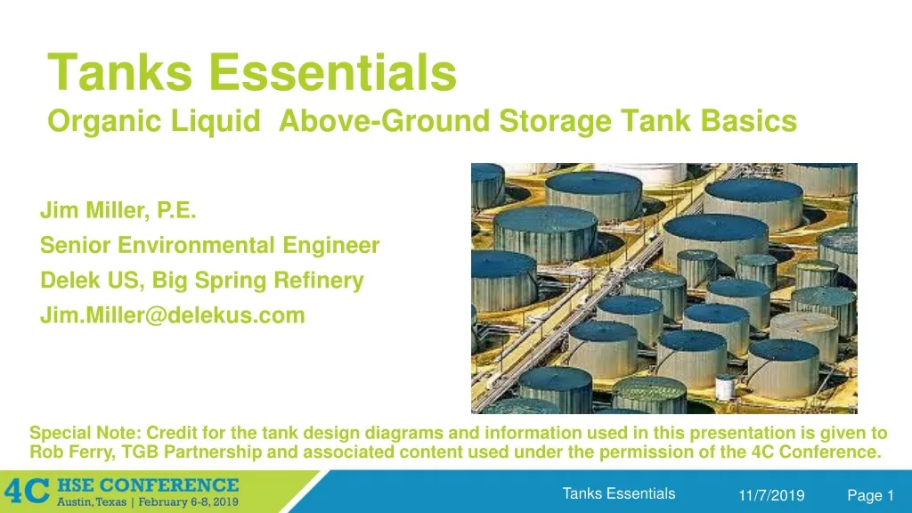
Tanks Essentials Organic Liquid Above-Ground Storage Tank Basics. Jim Miller, P.E. Senior Environmental Engineer Delek US, Big Spring Refinery Jim.Miller@delekus.com. Bart Leininger, P.E. Principal Ashworth Leininger Group Camarillo, CA.

E N D
Tanks EssentialsOrganic Liquid Above-Ground Storage Tank Basics Jim Miller, P.E. Senior Environmental Engineer Delek US, Big Spring Refinery Jim.Miller@delekus.com Bart Leininger, P.E. Principal Ashworth Leininger Group Camarillo, CA Special Note: Credit for the tank design diagrams and information used in this presentation is given to Rob Ferry, TGB Partnership and associated content used under the permission of the 4C Conference.
Objectives • Exposure to Tank Design Parameters • Understand Source Emissions Driving Forces and Calculation Basics • Evaluate Standard Practices for Emission Rate Determination • Introduction to Federal Regulatory Requirements
Tank Categories API 650 • 0 to 2.5 psig, “atmospheric tanks” API 620 • Up to 15 psig, “low-pressure tanks” ASME Boiler and Pressure Vessel Code, Section 8 • Above 15 psig, “pressure vessels”
Tank Design • Types of Above-Ground Organic Liquid Storage Tanks • Fixed-roof, IFR, EFR, Domed EFR • Types of Floating Roofs • IFR/EFR, bolted/welded, contact/noncontact • Floating Roof Design Details • Deck Seams, Rim Seals, Fittings
Types of Above-Ground Storage Tanks • Fixed-roof • Fixed roof at the top of the shell; no floating roof • Internal floating roof (IFR) • Fixed roof and a light-duty floating roof • External floating roof (EFR) • Open top (no fixed roof), with a floating roof • Covered (Domed) external floating roof • Fixed roof and an external-type floating roof
Fixed-Roof Tanks • No floating roof • Liquid surface is free to evaporate into the headspace • Typically low-profile cone roof supported with columns • Requires interior supports, frangible joint • Vented to the atmosphere • Open vents (gooseneck) or P/V breather vents
Fixed-Roof Tank Driving Forces for Emissions: Working Losses
Fixed-Roof Tank Driving Forces for Emissions: Standing Losses
Internal Floating-Roof Tanks (IFRTs) • Floating roof covers the liquid surface • Greatly reducing free evaporation into the headspace • Fixed roof is freely vented • For maintaining vapors << LEL (unless gas blanketed) • Floating roof deck is lightweight, per API 650, App. H • Protection by the fixed roof allows lightweight design • Some vapors escape past the floating roof • At rim seals, deck fittings, & deck seams (if bolted)
IFRT Summary • Deck construction can be lightweight • Short sleeves (housings) for deck support legs • Deck seams may be bolted (typ. for aluminum) • Fixed roof may require support columns • Which penetrate the deck, creating paths for emissions • Wind is not a factor in emissions • Vapors escape past the floating roof independent of ambient wind speed, and daily breathing results in enough air movement to carry vapors out of the tank
External Floating-Roof Tanks (EFRTs) • Floating roof covers the liquid surface • Greatly reducing free evaporation • Fixed roof is subject to wind action • Tank shell provides a partial shield, but losses still wind driven • Floating roof deck is heavyweight, per API 650, App. C • Designed for external forces (e.g., snow, torrential rain) • Some vapors escape past the floating roof • At rim seals, deck fittings (but deck seams are welded)
EFRT Summary • Deck construction is heavyweight • Tall sleeves (housings) for deck support legs • Welded deck seams • No fixed roof; no support columns • Typically fewer deck penetrations than for an IFRT • Wind is a factor in emissions • The rate at which vapors escape past the floating roof is very sensitive to ambient wind speed • Wind action offsets lower loss factors, fewer fittings
Covered (Domed) External Floating-Roof Tanks • Differs from IFRT in the type of floating roof • EFR-type deck, w/ welded deck seams, tall leg sleeves • Fixed roof is freely vented (as for IFRT) • Typically an aluminum dome over an EFRT • Particularly for retrofit applications, where a dome can be installed in-service • Could be a steel cone roof, but this would typically involve installing out-of-service, roof support columns
Domed External Floating-Roof Tank Summary • Deck construction is heavyweight • Tall sleeves (housings) for deck support legs • Welded deck seams • Typically with dome roof; no columns • Means typically fewer deck penetrations than for an IFRT • Wind is not a factor in emissions • Lower loss factors, fewer fittings, and not subject to wind action – lowest emitting type of construction.
Floating Roof Tank Driving Forces for Emissions: Working Losses
Floating Roof Tank Driving Forces for Emissions: Standing Losses
Floating Roof Features • Emissions sources • Withdrawals • Deck Seams (bolted decks only) • Rim Seals • Deck Fittings • Controls • Rim Seals • Deck Fittings
Floating Roof Considerations • Design: • External floating roofs per API 650, Appendix C • Internal floating roofs per API 650, Appendix H • Costs • Environmental • Fire Safety
External Floating Roofs • Potentially more economical to initially construct versus IFR • But future costs may be unacceptable: • Problems associated with water intrusion • Drain lines pose maintenance problems • Snow load poses maintenance problems • Higher liquid surface temp = higher emissions • This is not presently accounted for in the emission factors, but an API study is seeking to quantify this
Floating Roof Considerations • Design: • External floating roofs per API 650, Appendix C • Internal floating roofs per API 650, Appendix H • Costs • Environmental • Fire Safety
Fixed Roofs for Floating Roof Tanks • Steel cone roof • Typically column supported • Requires painting for maintenance • Retrofit installation requires out-of-service • Aluminum dome roof • Self-supporting (no interior columns) • No painting necessary • Retrofit installation may be done in-service
Problems with Support Columns • Increased air emissions • Due to penetrations through the floating roof • May involve significant foundation costs • Soft soils may require piles under each column. • High corrosion potential/unable to inspect • Bottom corrosion & leaks are accelerated at columns • Interfere with secondary bottom installation
Limitations for Pan-Type • Does not meet NFPA 30 criteria • Nor does the bulkheaded, as noted in the prior table - they do not have enclosed flotation compartments • Does not provide redundant buoyancy • A single leak can flood the entire deck, whereas other designs still float with two flooded compartments. • Is readily sunk by upsets or turbulence • Unsymmetrical loading may buckle the rim of the deck, allowing it to fold up like a taco. • Foam system must be for full surface area.