Download
1 / 47
830 likes | 2.08k Views
Electro-Optic Materials and Devices. Basic Concepts : Electrons (electronics), Photons (photonics) and Electro-Optics Basic Device Structures : Stripline devices; cascaded prism and superprism devices; ring resonators and photonic bandgap devices. More complex device structures

E N D
Electro-Optic Materials and Devices • Basic Concepts: Electrons (electronics), Photons (photonics) and Electro-Optics • Basic Device Structures: Stripline devices; cascaded prism and superprism devices; ring resonators and photonic bandgap devices. • More complex device structures • Societal Impact (telecommunications, computing, aerospace) • Why organics? Bandwidth (frequency response) Electro-optic activity (signal-to-noise and dynamic range) Ease of processing and cost Cleaner and greener • Material design and production (The Science) Quantum mechanics—Molecular level Statistical mechanics—Supramolecular (nanometer) level Materials Processing and Device Fabrication
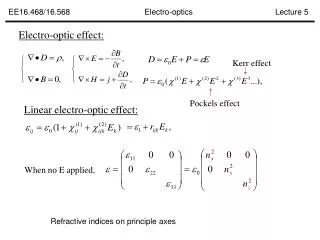
Basics: Matter & Energy (EM Radiation) • The fundamental constituents of matter are electrons, protons, and neutrons. Electrons are negatively charged, light weight particles that interact with electromagnetic (EM) radiation. Photons are the fundamental particles of EM radiation (light, microwaves, radiowaves, etc.) • Information (Signals) is transmitted either by electrons or photons. Electrons have strong interactions with each other—a factor that results in signal degradation (noise) when high frequency signals are transmitted or signals are sent over significant distances. Photons have very weak interactions making them ideal for high frequency signal applications and long range transport (e.g., telephone communication). • Manipulation of electrons in semiconductor materials is the basis of modern electronics. Manipulation of photons is the basis of fiber optic and wireless communication. • An electro-optic material is required to convert electrical signals into optical (photonic) signals (to go between the electronic & photonic signal domains)
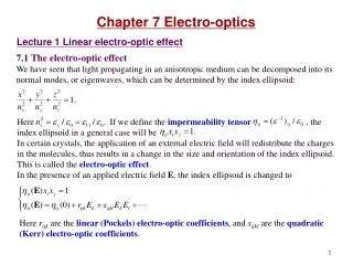
Electro-Optics: The Phenomena • An electro-optic material (device) permits electrical and optical signals to “talk” to each other through an “easily perturbed” electron distribution in the material.A low frequency (DC to 200 GHz) electric field (e.g., a television [analog] or computer [digital] signal) is used to perturb the electron distribution (e.g., p-electrons of an organic chromophore) and that perturbation alters the speed of light passing through the material as the electric field component of light (photons) interacts with the perturbed charge distribution. • Because the speed of light is altered by the application of a control voltage, electro-optic materials can be described as materials with a voltage-controlled index of refraction. Index of refraction = speed of light in vacuum/speed of light in material
Electro-Optic Devices: The on-ramps & interchanges of the information superhighway • The electro-optic effect can be used to transduce electrical information (signals) onto the internet (into optical signals). By slowing light down in one arm of the Mach Zehnder device shown below, the interference of light beams at the output can be controlled. Electrical information appears as an amplitude modulation on the optical transmission. This works equally well for analog or digital data. • l = optical wavelength • n = index of refraction • r33 = electro-optic coefficient • L = interaction length • = modal overlap integral d = electrode gap The Mach Zehnder Interferometer Vp = ld/(2n3r33LG) DC bias electrode ground electrode Modulated Light Out Light In RF electrode Substrate
Spatial Light Modulator (SLM) Schematic Diagram q = n3r33(V/h)(L/d) • l = optical wavelength • n = index of refraction • r33 = electro-optic coefficient • L = interaction length (length of • base of cascaded prism) • = modal overlap integral h = electrode gap d = height of prism Literature Citations • Dalton, Steier, et al., “Polymeric waveguide prism based electro-optic beam deflector,” Opt. Eng., 40, 1217-22 (2001) • Dalton, Steier, et al., “Beam deflection with electro-optic polymer waveguide prism array,” Proc. SPIE, 3950, 108-116 (2000) • Dalton, Steier, et al., “Polymeric waveguide beam deflector for electro-optic switching,” Proc. SPIE, 4279, 37-44 (2001)
High Bandwidth Optical Switches (The Electrical Problem) Two bands approach: • DC-65 GHz direct modulation, use one modulator section; • 65-130 GHz using up-conversion scheme, RF applied to one modulator section, and LO applied to the other section. Steier, Bechtel, Dalton et al., Proc. SPIE, 4114, 58-64 (2000).
Au upper modulation electrode Complementary modulated output Modulated output Input Au Au UFC 170 3mm SU-8 4.5mm CLD1 CLD1 5mm UV15 Au Si CROSSECTION GND POLYMER MICRO-PHOTONIC RING RESONATOR USING ELECTRO-OPTIC POLYMERS • Why Polymers? • Wide range of indices of refraction • Easy fabrication on multiple levels and integration with other devices • Voltage tunable filter or switch/ modulator using electro-optic polymers • Compact structure; size limited by index contrast • Temperature tuning, 0.1nm/C (use as an advantage or eliminate by athermal design • in which thermal expansion of polymer substrate balances dn/dT of waveguide)
Integrated WDM Transmitter Receiver Gold ground GND Au Electrode SU-8 Dalton, Steier, et al., J. Lightwave Technology, 20, 1968-75 (2002) Eye diagram 10 Gb/s, Vpeak = 1 V Device has ~15GHz BW
M = d1/(d1-d2) = DlDR/Dl1 Widely Tunable Polymer Double Micro-Ring Output waveguide T d1 d2 Input waveguide l The wavelength of maximum transmission from input to output occurs when both micro-rings are resonant. If the wavelength of one of the rings is tuned by Dl, the wavelength of maximum transmission tunes by MDl where Optical output spectra of the polymer DR tuned laser We have demonstrated both voltage (electro-optic) and thermally tuned polymer double micro-rings and Demonstrated an oscillator tuning across the band of the Erbium amplifier (1520-1560nm). d1 = 240mm, d2 = 246mm, M = 40 Side mode suppression >30 dB Voltage tuning 0.1nm/V, Thermal tuning 0.6nm/mW
100 Gbit/sec Analog-to-Digital Converter(1 of 2 approaches) • Dalton, Steier, Fetterman, et al. “Time stretching of 102 GHz millimeter waves using a novel 1.55 mm polymer electrooptic modulator,” IEEE Photonics Technology Letters, 12, 537 (2000)) • Dalton, Steier, Fetterman, et al. “Photonic time-stretching of 102 GHz millimeter waves using 1.55 mm polymer electro-optic modulator,” Proc SPIE, 4114, 44 (2000).
High Bandwidth Oscillators (Signal Generators) Optical Spectrum Analyzer Polarizing 2x2 Beamsplitting Cube Coupler Diode Pumped Nd:YAG Laser (1.3 µm) l Optical /2 Collimating Plate Isolator Lens 20 dB Coupler PD Spectrum YIG Tuned Low Noise Analyzer Bandpass Filter Amplifier • Dalton, Steier, Fetterman, et al., “Photonic control of terahertz systems,” Terahertz Electronic Proceedings, 102-5 (1998) • Dalton, Steier, Fetterman, et al., “Electro-optic applications,” in Encyclopedia of Polymer Science and Technology (J. Kroschwitz, ed) Wiley & Sons, NY, 2001
Phased Array Radar with Photonic Phase Shifter (1 of 3 approaches) Dalton, Steier, Fetterman, et al., IEEE mW & Guided Wave Lett., 9, 357 (1999)
Many Other Applications •Optical gyroscopes(China Lake Naval Weapons Lab and Redstone Arsenal) •Acoustic Spectrum Analyzers (IEEE J. Sel. Topics in Quantum Electronics, 6, 810-6 (2000) •Various Sensors and Test Equipment (e.g., printed circuit board testers) •Antenna Structures, e.g., for Land Mine Detection •Terahertz signal generation and detection for a variety of applications
Electro-Optic Devices: The on-ramps & interchanges of the information superhighway(The Metro Loop and Fiber to the Home)
•Semiconductor Research Corporation Workshop on Optical Interconnects http://www.src.org/member/sa/nis/E002117_Opto_wksp.asp •British House of Lords Select Committee on Science & Technology Study of Innovations in Computer Processors •IEEE Computermagazine (“Data at the speed of light”, July 2002, p. 24) •High frequency, ultra high stability clocks •On-chip signal distribution (not necessarily Fiber to the Processor)—IEEE Spectrum •Chip-to-chip interconnection •Module-to-module interconnection Critical to Next Generation Computing
Copper Versus Fiber (Analysis Courtesy of IBM - private communication from Alan Benner) Ratio of Optical to Electrical Performance Key Metrics Use Optics Use Optics Use Optics for for Perf & Cost for Performance Performance 1000 1000 100 100 Optical better 10 10 1 1 Ratio Optical to Electrical Performance Cost 0.1 0.1 Power Electrical better Edge density Areal density 0.01 0.01 Cable density conservative optimistic 0.001 0.001 2002 2005 2008 2002 2005 2008 Backplane, <1 meter Cabled, 10 meters
Critical to Aerospace Industry (Courtesy of Boeing) U Washington Caltech
Motivation for use of photonics in RF systems: •Performance (Bandwidth, arrayability, voltage requirements, immunity to EMI) •Weight savings (Replacement of coaxial cable with fiber) •Cost savings (compatible with semiconductor VLSI fabrication) Electro-Optic Polymers for RF Photonics – a Key Technology (Courtesy of Dr. Susan Ermer of Lockheed Martin Palo Alto)
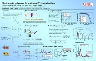
Why Organic Electro-Optic Materials (Devices)? •Intrinsic material bandwidths of several hundred gigahertz. The response time (phase relaxation time) of p-electrons in organic materials to electric field perturbation is on the order of femtoseconds. Operational 3 dB bandwidths of 200 GHz have been demonstrated for modulators & switches •Organic electro-optic coefficients are currently 2-4 times higher than lithium niobate and getting larger. Theoretically-inspired rational design of materials will keep electro-optic activity improving for several years. Device operational voltages of less than 1 volt can be routine. •Organic EO materials are highly processable into 3-D circuits and can be easily integrated with semiconductor VLSI electronics and silica fiber optics. Low loss coupling structures can be straightforwardly fabricated. •Cleaner and Greener (Environmental Health Perspectives, vol. 111, no. 5, May 2003, pp. A288-291) .
The Bandwidth Potential (private communication from Howard Katz and Mark Lee) M. Lee and co-workers, Science, 298, 1404 (2002). Abstract of an article published in Science by Lucent researchers “A major challenge to increasing bandwidth in optical telecommunications is to encode electronic signals onto a lightwave carrier by modulating the amplitude of the light up to a very fast rate. Polymer electro-optic materials have the physical properties necessary to function in photonic devices beyond the current 40 GHz state-of-the-art bandwidth. We show that an appropriate choice of polymer materials can effectively eliminate all dielectric factors contributing to the decay of an optical modulator’s response at high frequencies. The resulting device modulates light with a bandwidth between 150 to 200 GHz and is capable of producing detectable modulation signal at 1.6 THz. These rates are faster than commercial bandwidth requirements for the foreseeable future.”
What are the critical requirements for EO materials and devices? • Low halfwave voltage is a critical requirement in externally modulated photonic systems: • Analog systems: For RF transparency: • Link gain 1/Vp2 • For high dynamic range: • NFVp2 • (low level signal detection limited by noise floor) • Digital systems: • High speed digital circuits have low output voltage • Digital amplifiers very costly • Bandwidth is the other critical requirement!
Table. Comparison of Electrooptic Modulator Performance Parameters of NLO Materialsa Parameter LiNbO3 NLO Polymer NLO Polymer NLO Polymer (2001-2002) (current) (in 18 months) ______________________________________________________________________________________________________ reff, pm/V 30 50 130 300 n3(reff)b 330 225 584 1,348 e 30 3 3 3 n3(reff)/ e b10 75 195 450 lengthbandwidth product, GHzcm 7 >100 >100 >100 VpL, Vcm 5 2.5 0.9 0.4 optical loss, dB/cm 0.2 0.2-1.0 0.2-1.0 0.2-1.0 _____________________________________________________________________________________________________ aAt optical wavelength of 1.3 microns. bValues given are figures of merit.
Optimization of Molecular HyperpolarizabilityQuantum Mechanics is the Key! How far have we come? How far can we go? Take home observation: Molecular electro-optic activity is enormous and getting larger. If molecular electro-optic activity could be translated to macroscopic (material) activity, electro-optic coefficients greater than 1000 pm/V would be achieved.
Systematic Improvement in Molecular Electro-Optic Activity: Variation ofmb(r33 = Nb<cos3q>f ~Nmbf/5kT(at low N andm)
Chromophore content: 20 wt% in APC Baking condition: 85 C overnight; Poling condition: 110 C and 65 V/m for 10 min. r33 = 101 pm/V at 1.55 m Dr. Sei-Hun Jang Postdoctoral Fellow (UW)
Condensation a -Hydroxyketone C N O L i C N O H O O O C N O E t F C C F 3 i, C N 3 2 O H C F C N 3 C F C F - T C F 3 3 ii, dilute HCl 70% Base Reaction time Yield (%) Condition Reflux L i O E t 48 h 30 Microwave N a O E t 20 min 55 Table. Comparison of conventional and microwave methodologies Breakthroughs in Organic Synthesis are Important Comparison of Microwave & Reflux Synthesis of CF3-TCF acceptor
C N C N O H N H C N C N Derivative with electron C N C O O E t C N deficient heterocyclic group C O O E t E t C N O H C N C N N H E t E t N H E t C N C N C N C N C N C N N O 2 C N N O 2 Focused Microwave-assisted Synthesis of Dihydrofuran Acceptors with Tunable Electron-withdrawing Strength Microwave accelerated step-wise control of imine intermediate O + O Electron withdrawing strength tunable dihydrofuran acceptors O O N O N S + N O N O O N Electron with-drawing strength O O S N O N + O O
Optimization of Macroscopic Electro-Optic Activity(Currently, we can utilize only 1 to 9 percent of the electro-optic activity of a chromophore molecule—Statistical mechanics is the answer to improving this figure)Statistical Mechanics is the answer! Simple chromophore/polymer composites. Covalently coupled systems (dendrimers, dendronized polymers, “new” side chain polymers) where we need to worry about restrictions placed on motion by covalent bonds and non-bonding (secondary, tertiary) interactions.
C N N O C N 2 M e N A c O 2 C N C N D R A c O N C H O C N P h C N O H A P I I A c O N C P h C N C N C N C N A c O C N N C C F ( C F ) C F B u N S O 2 2 5 3 2 2 A c O N C N C C N A c O A c O P h B u B u F T C MATERIAL ISSUES: Translating Molecular Optical Nonlinearity into Macroscopic Electro-Optic Activity EO coefficient is not a simple linear function of chromophore loading. Curves exhibit a maximum. Why? N N S . N TCI 1 . 0 O O N N N S 0 . 8 3 3 O O N N S 0 . 6 N S ISX 0 . 4 S N S - 4 8 m b T C I = 6 0 0 0 x 1 0 e s u 0 . 2 FCN - 4 8 m b I S X = 2 2 0 0 x 1 0 e s u SDS - 4 8 m b D R 1 9 = 5 5 0 x 1 0 e s u 0 . 0 N N O S O O N APTEI 0 1 0 2 0 3 0 4 0 Chromophore loading wt%
Translating Microscopic to Macroscopic Electro-Optic Activity Chromophore-poling Chromophore-Chromophore Thermal Randomization Field Interaction Electrostatic Interaction E Acentric Ordering Isotropic Centric Ordering 3 3 q q m <cos > = F/5kT <cos > = m = f(0)E p/5kT 2 m ( F/5k T)[1 -L (W/ kT)]
Comparison of Theory & Experiment EO Activity Depends On Shape! Experiment—Solid Diamonds
F F O F F F O F O O C N N C N O O S O N C O N C O O O O O O O C N O O C N O S O O N C N N C O O F O O F F F O F F O O N O F O O F F S O N C O C N O O F N C C N O F F O Dendrimers—3 D Organization of Chromophores By choosing a tilt angle for the three chromophores (~60°) the experimental enhancement (of ~ 2 fold) was realized. Statistical Mechanical Theory explains the improved performance of dendritic chromophores.
Center Full Dendrimer (AJ3) • Three chromophores -- 20 Debye dipole each • Best of Set of accepted M.C. moves. • Near perfect order of 3 Chromophores • Very Large Field ( 3000 MV/m) Points on Z (up) Magic Angle Chromophore
Dendritic NLO chromophore Side-Chain dendronized NLO polymer Various Dendritic Structures x y x y . NLO dendrimer : NLO chromophore moiety : Polymer backbone : Core moiety : Dendritic moiety : Crosslinkable moiety
Strategy to Achieve Cylindrical Shape Conformation in NLO Synthetic Supramolecular Systems Dendritic Crosslinker Dendritic NLO Chromophore tobacco mosaic virus
Dendrimers permit great synthetic flexibility—e.g., Fluorination Dendronized chromophore yields 3 times the electro-optic activity and reduced optical loss (next figure). Optical loss comes from protons .
Auxiliary Properties: Optical Loss including both absorption and scattering loss 0.6 TE Mode 0.5 0.4 Loss (dB/cm) 0.3 0.2 0.1 0.0 1470 1490 1510 1530 1550 1570 1590 Wavelength (nm)
z x y OH free-radical copolymerization with methyl methacrylate and 1. spin cast with hydroxyethylmethacrylate diisocyanate crosslinker 2. electric field poling 3. thermal crosslinking HO OH HO OH 3-D crosslinked network THERMAL STABILITY—The Need to Lock-In Poling Induced Acentric Order: Intermolecular Crosslinking
CH CH 3 3 CH 3 CH H C 3 3 Ultra low optical loss high temperature polymer: m (< 0.2 dB/cm @ 1.55 m) Crosslinkable PFCB Thermoset Systems F F F F O O O O F F F F F F F F O F O F F F F F F F O O F F F F F O F F F F F O F O F F O O F F F F New method avoids Sensitivity to atmospheric moisture! F F O O F F F F F F • Good thermal stability (Td~470 °C) • Excellent optical transparency • (< 0.25 dB/cm at 1.55 m) • Low dielectric constant (k~2.35, 10 kHz) • Low moisture absorption • High glass-transition temperature (Tg~380 °C) • (0.021% after 24 hrs soak in water) • Low birefringence
Processability: An Advantage of Organic Electro-Optic Materials •The tailorability of organic materials and particularly of dendrimers permits integration of organic EO materials with virtually any material (silicon, silicon dioxide, Mylar, III-V semiconductors, metals, etc.) •Hardened organic EO materials are amenable to reactive ion etching (RIE) and to various photolithographic processes. Processing is very compatible with semiconductor processing techniques. •Organic materials are quite robust (high dielectric breakdown, good thermal stability at most processing temperatures, high radiation (gamma, high energy particle) damage thresholds, etc. •Likely amenable to high volume manufacturing using processing techniques such as spin casting and dry etching. •Straightforward fabrication of an array of prototype devices.
Reactive Ion Etching of 3-D Optical Circuits UV Spin-Casting Preserves Oxygen Surface Contour Ions Photoresist Cladding Core Cladding Substrate Variable Photoresist RIE Slope Waveguide Exposure Transfer Completion
Fabrication: Shadow Etch Oxygen Ions • Shadow Masking of Ions • Angle µ RF Power, Gas Pressure, Time, Mask Dimensions • Angles: 0.1-3° • Heights: 1-9mm • Lengths: 200-2,000mm • Fast Prototyping • Various Angles From Single Mask • No Extensive Fabrication Steps • Repeatable Quality Mask Offset Polymer 6 4 m Height (m) 2 0 0 400 800 1200 1600 Length (mm)
Tapered Transitions: Minimization of Coupling Loss n(active) > n(passive) small length Þ material loss ß large length Þ radiation loss ß
Fabrication of 3-D Integrated Active/Passive Optical Circuits