Download
1 / 14
140 likes | 157 Views
Discover the innovative Solid State RF System developed by Raja Ramanna Centre for Advanced Technology (RRCAT) to characterize Superconducting RF cavities. This system enables testing and characterization of Niobium cavities at cryogenic temperatures, quantifying quality factors and accelerating gradients. The RF Data acquisition and control system interface various instruments via GPIB and Multifunction DAQ card, operated with LabVIEW software. Explore the functionality, performance, and testing procedures of this cutting-edge RF system.

E N D
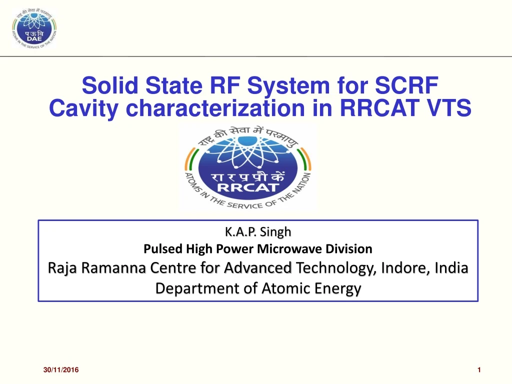
Solid State RF System for SCRF Cavity characterization in RRCAT VTS K.A.P. Singh Pulsed High Power Microwave Division Raja Ramanna Centre for Advanced Technology, Indore, India Department of Atomic Energy 30/11/2016 1
Solid State RF System for SCRF cavities tests in VTS • RRCAT has developed a vertical test stand for testing and characterizing the SCRF cavities made of Niobium (1.3GHz/650MHz) at cryogenic temperatures. • These tests are performed on an undressed cavity to quantify the quality factor (Q) and the accelerating gradient (Eacc). • VTS RF Data acquisition and control system is based on interfacing of different instruments via GPIB and Multifunction DAQ card on PXI bus and PXI controller with LabVIEW based DAQ/control software which calculates the quality factor (Q) and the accelerating gradient (Eacc). 1.3 GHz VTS LLRF systems 30/11/2016 2
1.3 GHz & 650MHz VTS RF system developed at RRCAT • 500W SSPA at 1.3GHz, 650MHz and 325MHz have been designed, developed and tested for characterizing the SCRF cavities in VTS at RRCAT. • Both the 650MHz and 1.3GHz high power amplifiers have been used during the single cell cavity tests and their performance was satisfactory. 650 MHz LLRF system developed at RRCAT 1.3 GHz system and 500W SSPA installed in VTS RF system in control room 650 MHz, 500W SSPA installed at RRCAT VTS site 30/11/2016 4
LabVIEW VI for VTS 30/11/2016 5
Cavities developed at RRCAT Various prototype 1.3 GHz Single cell cavities developed at RRCAT 1.3 GHz cavities Mounted on the VTS 650 MHzSingle cell cavities developed at RRCAT 6
VTS Test procedure • Measure the cavity’s resonant frequency. • Zero the power meters. • Calibrate cables. 30/11/2016 7
VTS Test procedure continued…. • Find optimum phase for locking. • Determine the cavity coupling. • Perform Decay measurement to calculate Qext2. • Measurement of CW parameters. 8
Results 9
Results 10
Test results of single cell Nb SRF cavity 1.3GHz at RRCAT VTS at 2K & 1.8K on 31 JAN 2014 Quench @36.7MV/m Quench @36.2MV/m 30/11/2016 11
Cavity Quench Transmitted power waveform during cavity quench shown above. The sharp fall indicate the cavity has lost its superconductivity and its stored energy decays very fast, after which the cavity cools down and start slowly filling once again (exponential rise), reaches its maximum Eacc and quenches after some time once again. 30/11/2016 12
Cable calibration experiment For the test of the linearity of the cable calibration the input power was ramped up to 125 W and fed into the detuned PC2 LHC cavity. The incident power (Pi) and reflected power (Pr) were measured using the initial cable calibration constants. Ratio of Pr/Pi changes more than 2.5 % as we go up to 125 W. So in order to get better power value readings, online calibration of the input cable is suggested. 13