Download
1 / 40
1.34k likes | 3.21k Views
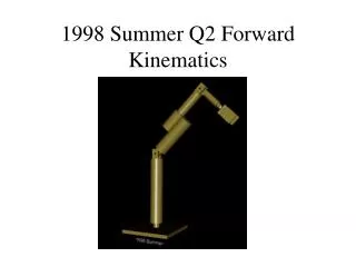
Introduction to ROBOTICS. Forward Kinematics. University of Bridgeport. Kinematic. Forward (direct) Kinematics Given: The values of the joint variables. Required: The position and the orientation of the end effector. Inverse Kinematics

E N D
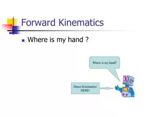
Introduction to ROBOTICS Forward Kinematics University of Bridgeport
Kinematic • Forward (direct) Kinematics • Given: The values of the joint variables. • Required: The position and the orientation of the end effector. • Inverse Kinematics • Given : The position and the orientation of the end effector. • Required : The values of the joint variables.
Why DH notation • Find the homogeneous transformation H relating the tool frame to the fixed base frame
Why DH notation • A very simple way of modeling robot links and joints that can be used for any kind of robot configuration. • This technique has became the standard way of representing robots and modeling their motions.
DH Techniques • Assign a reference frame to each joint (x-axis and z-axis). The D-H representation does not use the y-axis at all. • Each homogeneous transformation Ai is represented as a product of four basic transformations
DH Techniques • Matrix Ai representing the four movements is found by: four movements
DH Techniques • The link and joint parameters : • Link length ai : the offset distance between the Zi-1 and Zi axes along the Xi axis. • Link offset di the distance from the origin of frame i−1 to the Xi axis along the Zi-1 axis.
DH Techniques • Link twistαi :the angle from the Zi-1 axis to the Zi axis about the Xi axis. The positive sense for α is determined from zi-1 and zi by the right-hand rule. • Joint angle θi the angle between the Xi-1 and Xi axes about the Zi-1 axis.
DH Techniques • The four parameters: ai: link length, αi: Link twist , di : Link offset and θi : joint angle. • The matrix Ai is a function of only a single variable qi , it turns out that three of the above four quantities are constant for a given link, while the fourth parameter is the joint variable.
DH Techniques • With the ith joint, a joint variable is qiassociated where All joints are represented by the z-axis. • If the joint is revolute, the z-axis is in the direction of rotation as followed by the right hand rule. • If the joint is prismatic, the z-axis for the joint is along the direction of the liner movement.
DH Techniques 3. Combine all transformations, from the first joint (base) to the next until we get to the last joint, to get the robot’s total transformation matrix. 4. From , the position and orientation of the tool frame are calculated.
Example I The two links arm • Base frame O0 • All Z ‘s are normal to the page
Example I The two links arm Where (θ1 + θ2 ) denoted by θ12 and
Example 2 19
Example 2 20
Example 5The three links cylindrical with Spherical wrist • given by example 2, and given by example 3.
Example 5The three links cylindrical with Spherical wrist • Forward kinematics: 1. The position of the end-effector: (dx ,dy ,dz ) 2. The orientation {Roll, Pitch, Yaw }
Roll Pitch Yaw • The rotation matrix for the following operations: Z Y X
Example 4The three links cylindrical with Spherical wrist • How to calculate • Compare the matrix R with Of the matrix
HW • From Spong book: page 112 • 3.2, 3.3, 3.4, 3.6 , 3.7, 3.8, 3.9, 3.11 • No Class on next Tuesday
Module 1 • Where are Roll, Pitch, and Yaw
Representing forward kinematics • Forward kinematics • Transformation Matrix
Remember • For n joints: we have n+1 links. Link 0 is the base • Joints are numbered from 1 to n • Joint i connects link i − 1 to link i. • Frame i {Xi Yi Zi} is attached to joint i+1. • So, frame {O0 X0 Y0 Z0}, which is attached to the robot base (inertial frame) “joint 1”.