Download
1 / 24
270 likes | 495 Views
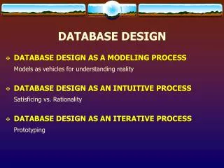
Database Design (Data Modeling). DCO11310 Database Systems and Design By Rose Chang. Analysis. Design. Implement. Testing. Production. System Development Life Cycle. Object-Oriented DBMS. ODL, UML, etc. Ideas. Relational DBMS. Relations. ER. Data Modeling.

E N D
Database Design (Data Modeling) DCO11310 Database Systems and Design By Rose Chang
Analysis Design Implement Testing Production System Development Life Cycle
Object-Oriented DBMS ODL, UML, etc. Ideas Relational DBMS Relations ER Data Modeling • A particular way of representing data • Analysis of what information the database must hold • Relationships among components of that information
Oracle server Data Models Entity model ofclient’s model Model ofsystemin client’smind Table modelof entity model Tables on disk
Why Use Data Modelling ? • Programming relies very much on data model • Provides a method to reconcile the very different end-user views of the nature and role of data • Helps us to understand the complexity of a real world data environment • Yields a proper “blueprint” of the database design
Steps in Data Modelling Analysis of Requirements Entity Relationship Modelling Transformation into Data Structures Normalisation of Data Structures
Requirement Analysis • Must incorporate all necessary information from different major users • Identify data requirements • Description of data used or generated • Details of how data is to be used and generated • Describe information to be recorded • Combine into a single global view • Analyse the types of transactions to be performed
ER Modelling of Requirements • Construct an ER model to describe the data objects and their interrelationships • Identify key attributes • Decide on the functionality of relationships (mandatory or optional) • Construct a schematic ER model which gives a global view of the entire database
Transformation of the ER Model to a Schema • Map the ER model onto a set of data structure, or schema • Schema : the description of the organization of a database seen by the DBA
Normalisation of the Schema • Reduce each relation to the highest stage of normalisation • BUT designer may wish to refine the resultant schema in order to improve processing efficiency
Logical vs. Physical DB Design (II) Views Selected and derived tables and columns Program Data Logical DB Design Physical DB Design Tables and columns How the data is stored in the computer
Components of Database Design • The four representations or abstractions will progressively get more details of the system : • Data requirements (Textual Information) • Conceptual data model (E-R Model) • Logical schema (Normalized Entity) • Physical Storage schema (Create Table Statements)
Conceptual Data Model (I) • Identify entity types • Identify relationship types • Identify and associate attributes with entity or relationship types • Determine attribute domain • Determine candidate, primary and alternate ket attributes
Conceptual Data Model (II) • Validate conceptual model against user transactions • Review conceptual data model with user
Entity-attribute-relationship Models (EAR) • Used to produce conceptual data model • Consists of : • A formal description of each entity in terms of its attributes • Descriptions of the meanings of relationships • Descriptions of any constraints • The ER diagram
DEPARTMENT number name location EMPLOYEE number name job title have Child entity Parent entity Entity Relationship Model • There are many notations for ERD such as UML, Chen, Crow’s feet • Create an entity relationship diagram from business specifications or narratives • A department have many employee
Entities Relationship • Define associations among entities • All relationships are bi-directional • Degrees of relationships • One-to-one relationship (1:1) • One-to-many relationship (1:M) • Many-many relationship (M:N)
Student-id Student-name Course-code Account-id usage password Student Email have Student-id Student-name Program-code Student Program Program-code Program-name have Degrees of Relationships One-to-one Relationship One-to-many Relationship Detail Entity Master Entity
Student-id Student-name Program-code Course-code Student Course Course-code Course-name take have Many-to-many Relationship You should resolve it by adding link entity Master Entity Master Entity Course Course-code Course-name Student-id Student-name Program-code Student Student-id Course-code mark for belong to Mark get have Link Entity
Optional vs. Mandatory Relationship “A lecture may teach one or many courses.” “A course must be taught by only one lecturer.” Lecturer Course teach
Draw an ERD • Each company operates four departments, and each department belongs to one company. Each department employs one or more employees, and each employee works for one department. Each of the employee may or may not have one or more dependants, and each dependant belongs to one employee. Each employee may or may not have an employment history