Download
1 / 12
120 likes | 144 Views
Explore advanced methods for accurate polarization measurement in solar observations using matrices and calibration optics.

E N D
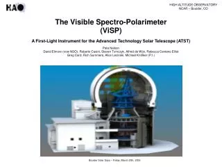
ViSP Polarimetry David Elmore HAO/NCAR Elmore@ucar.edu
Polarization Measurement The measured Stokes vector is the product of the polarimeter response matrix and telescope matrix acting upon the input Stokes vector from the Sun. To achieve the required accuracy, the uncertainty in XTmust be less than some value, but not all elements need to be less than the polarimetric accuracy requirement. ViSP Polarimetry 2
Requirement Matrix# Uncertainty in a measured normalized Stokes parameter is due uncertainty in gain, a, and uncertainty in cross talk among Stokes parameters, b. For the ith Stokes parameter DPi=aPi+bPj≠i . For cross talk among the polarization parameters the uncertainty in the measurement of the ith parameter due to the jth Stokes parameter, bPj≠i must be less than the polarimeteric accuracy requirement, e. For cross talk into I, bPj≠1= aPj≠1. # from Kioshi Ichimoto NAOJ ViSP Polarimetry 3
Requirement Matrix Combine the four perterbation equations into a matrix and scale the cross talk elements by typical polarization signals Where pl and pv are ‘typical’ normalized solar polarization signals, pI = 1 ViSP Polarimetry 4
Requirement Matrix For ATST we have no gain requirement, but 1% is typical, therefore a = 0.01 The polarization accuracy requirement e = 5 x 10⁻⁴ From experience with ASP, ‘typical’ values for solar polarization are, pl = pv = 0.1. Substitution into the requirement matrix gives The requirement matrix gives the accuracy to which we need to know [XT]. ViSP Polarimetry 5
Measurement of XT • Use calibration optics for both X & T (ASP at DST) • Calibration polarizers between polarimeter and telescope for X (In the GOS for ATST) • Calibration polarizer over the telescope for T • Calibrate X, Model T • Calibration polarizers between polarimeter and telescope for X • Create a two mirror telescope model and use some external measure of unknowns in model such as of the complex refractive index of the mirror coating ViSP Polarimetry 6
Measurement of XT • Calibrate X, determine T using solar spectra • Calibration polarizers between polarimeter and telescope for X • Create a model T and use solar spectra to fit the unknows factors in the model • Determine X and T from solar spectra • Create a model of XT and use solar spectra to fit the unknown factors in the model • Use different techniques for different [XT] matrix elements ViSP Polarimetry 7
Cross talk into Intensity Use flat field for 1,1. For remainder of first row, a simple model of XT will suffice ViSP Polarimetry 8
Cross talk from I to Q, U, and V Use solar continuum polarization (Standard operating procedure for ASP) ViSP Polarimetry 9
Scale and phase Calibration polarizers between X and T. The effect of T is small so a simple model will suffice. ViSP Polarimetry 10
Cross talk between U and V Use an accurate model of the telescope supported by external refractive index data or use solar spectra ViSP Polarimetry 11
pau ViSP Polarimetry 12