Download

1 / 21
210 likes | 249 Views
Explore methods for precise beam profile measurements in high-energy linacs within 10%, including Residual Gas Luminescence and Residual Gas Ionization. Evaluate detection of ions and electrons for cross-sectional accuracy.

E N D
Non-Invasive Beam Profile Measurement Overview of evaluated methods
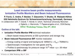
Goal • Beam profile measurements in the high-energy part of the linac • Requirements: • The beam profile should be measured within 10% for nominal beam width. • The beam profile might be measured over a beam pulse or even over several pulses combined. The overall integrating time must not exceed several (5) seconds.
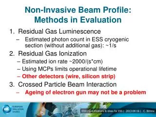
Methods in Evaluation • Residual Gas Luminescence • Residual Gas Ionization • Detection of Ions • Detection of Electrons • Crossed Particle Beam Interaction • Electron Beam • Ion Beam
1. Residual Gas Luminescence • Ion beam interacts with residual gas in a way, the gas emitts light • This light is detected and a profile calculated Picture: Balalykin, N. I. et al., Development of beam position and profile monitor based on light radiation of atoms excited by beam particles, Dubna, Russia: XIX Russian Particle Accelerator Conference, 2004.
1. Residual Gas Luminescence • Problem of this method: small cross section • Estimated photon count in ESS cryogenic section (without additional gas): <10/s
1. Residual Gas Luminescence • Amount of resulting photons depends on • Cross section (particle energy) • Amount of incoming protons • Residual gas density • Only residual gas density can be changed • A pressure of 10-9 mbar with 5% N2is assumed → 5*10-11 mbar N2 • Increase to 5*10-10 would boost countrate in a region, measurements can beachieved • Becauseofcryogeniccomponentsnearby additional gas might not bewanted.
1. Residual Gas Luminescence WS Detector Wire Scanner • Issues with vacuum components probable • Issues with shielding of wire scanner detector
1. Residual Gas Luminescence • Preferred method because of uncomplex setup • Low predicted countrate might turn this methodunfeasiblein coldsection • Atotherpositionsthismethodmightbe still preferedfor online profilemeasurement • Planned to test predictionsofcoldsectionat SNS in summer 2012
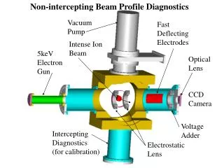
2. Residual Gas Ionization • Ion beam interacts with the residual gas in a way the gas gets ionized • Ions and/or electrons* are accelerated by an electric field towards a detector • Charge is multiplied and measured for profile determination
2. i. Residual Gas Ionization • Estimated count rate <450/(s*cm) • Using MCPs limits operational lifetime • Other detectors (wire, silicon strip) • Higher lifetime • Less resolution • Not symetrical voltage • Beam space charge might influence the beam imaging process
2. i. Residual Gas Ionization 160 kV/m, Proton, 9.96% drift 320 kV/m, Proton, 5.2% drift 320 kV/m, He+, 4.82% drift 640 kV/m, He+, 2.49% drift
2. i. Residual Gas Ionization • Space issues for fitting measurement for 2 plains in one box • 5 cm between WS and 1st plain • 5 cm between 2nd plain and wall • 7 cm between the two IPMs
2. ii. Residual Gas Ionization • For use of electrons a magnetic field must be overlayed • Additional magnets must be introduced to bend the beam back to its position. • This field must be in the region on 0.1 T • With a 0.5 m magnet this leads to roughly 1° bending angle of the beam.
2. ii. Residual Gas Ionization • Shown: GSI concept • At ESS the distance between corrector and main magnet isupto 13 m. • This leads to about 20 cm displacement of the beam Picture: Peter Forck, Minimal Invasive Beam Profile Monitors for High Intense HadronBeams, IPAC 2010 Kyoto
2. Residual Gas Ionization • Low imaging disturbance due to beam space charge • High speed measurements not requested • Magnetic fields for electrons add aditional complications • Result: Ionization monitor with electrons not prefered method
3. Particle Beam • A particle beam (electrons, ions) is send perpendicular to the ion beam • Due to coulomb interaction the particle beam is deflected • This deflection can be used to calculate the beam profile Picture: Peter Forck, Minimal Invasive Beam Profile Monitors for High Intense HadronBeams, IPAC 2010 Kyoto
3. Particle Beam • SNS uses electron beam to ‚scan‘ through the ion beam • Beam bunch length might be to short for this method at ESS • Particle „sheet“ might be a possibility.
3. Particle Beam • Rough illustration using ions to visualize the dimensions. • Beam consisting of electrons leads to a smaller setup
Conclusion • Luminescence might be hard to achieve for cold part, maybe useful at other positions • Magnets for ionization (electrons) add another layer of complexity, which is not necessary • Ionization (ions) and particle beam most promising for cold linac
Questions for discussion • Ionization: Changing EM-Fields and the influence on the ions? • Agreement with my conclusion? • Other possible methods not in evaluation yet? • ...