Download
1 / 75
810 likes | 1.17k Views
Curves and Surfaces. Jeff Burns July 5, 2004. Overview. Introduction to surfaces Fields, curves, and surfaces Representations Reconstruction Segmentation Registration. Introduction to Surfaces. Typically used to provide a model for depth measurements

E N D
Curves and Surfaces Jeff Burns July 5, 2004
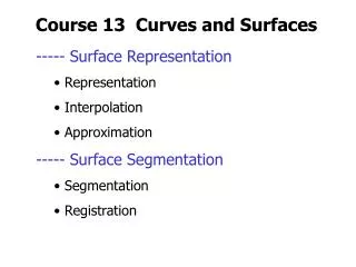
Overview • Introduction to surfaces • Fields, curves, and surfaces • Representations • Reconstruction • Segmentation • Registration
Introduction to Surfaces • Typically used to provide a model for depth measurements • Surfaces are interpolated or approximated from depth measurements • Surfaces are then segmented into regions with similar characteristics (curvature) • Discussion is similar to contours, which are 2D. Surfaces are 3D.
Importance of Surfaces • Representation of depth measurements • Analysis of depth measurements • Data visualization • Object recognition
Fields • Coordinate systems • Used to represent measurements, which are a mapping from the coordinate space to the data space • Image-related measurements include intensity and depth • Three types of fields are uniform, rectilinear, and irregular
Uniform Fields • Measurements stored in a rectangular grid • Equal spacing between rows and columns • Images – each grid square is a pixel
Rectilinear Fields • Data samples not equally spaced along the coordinate axes • Rectangular grid with varying distances between rows and columns
Irregular Fields • Contain scattered measurements not corresponding to a rectilinear structure • No overall organizational structure • Similar to coordinate systems used in standard mathematics
Importance of Fields • Allows for flexibility in the representation of measurements. • Example: • Depth measurements can be represented as displacement measurements in the uniform field of an image • Depth measurements can also be represented as points in the irregular field of three-dimensional space • The use of fields should become clearer later in the presentation
Extending Curve Geometry to 3D • Explicit form: • Implicit form: • Parametric form:
Geometry of Surfaces • Explicit form: • Implicit form: • Parametric form:
z P zP y x (xP, yP) Geometry of Surfaces • The explicit form is good for graph surfaces, which are surfaces represented as displacements from a coordinate plane • A graph surface represents a surface as displacements normal to the coordinate plane
Planes • Three points, p0, p1, and p2, define a plane • The normal vector to the plane, n, is defined as • The implicit equation for a plane is • a, b, and care the elements of n
Differential Geometry • Local analysis of how small changes in position in the planar domain affect the position on the surface, the first derivatives, and the surface normal • The first derivatives at a point are two orthogonal vectors that span the tangent plane • The surface normal at this point is the unit vector orthogonal to the tangent plane
Differential Geometry • Slicing the surface with a plane containing the normal vector produces an infinite number of normal curves, depending on the orientation of the slicing plane. • The minimum and maximum curvatures (principal curvatures) can be used to calculate the Gaussian curvature and mean curvature • Umbilic points are locations on the surface where all normal curvatures are equal (end of an egg)
Curve Representations • Mostly interested with 3D cubic splines • Sequence of polynomial curves joined end-to-end to represent a complex curve • Cubic polynomial curve: • Cubic spline:
Surface Representations • Polygonal Meshes • Surface Patches • Tensor-Product Surfaces
Polygonal Meshes • Planar polygons are combined to model the surface of an object • The winged edge data structure (WEDS) is used to store information regarding the mesh
Winged Edge Data Structure • Provides efficient means to find all faces that include a given vertex • Includes vertex, edge and face records • All faces using a vertex can be found in time proportional to the number of faces that include the vertex • All vertices around a face can be found in time proportional to the number of vertices around the face • Can handle polygons with many sides, and not all polygons in the mesh must have the same size • Compact data structure that allows for very efficient algorithms
Edge Vertex Winged Edge Data Structure • Vertex record • Contains the coordinates for the vertex • Contains a unique number for the vertex • Contains a pointer to the record for an edge that ends at that vertex.
Face Edge Winged Edge Data Structure • Face record contains a pointer to the edge record of one of its edges
Winged Edge Data Structure • Edge record • Provides most of the connectivity for the mesh • Contains pointers to each endpoint vertex • Contains pointers to the faces on either side of the edge • Contains pointers to the four wing edges that are neighbors in the polygonal mesh. These pointers allow traversal from edge to edge around a face.
Vertex Edge Edge N NW NE Edge Face Face W E Edge Edge Vertex SW SE S Winged Edge Data Structure • Edge record
Traversing a Face • Start at the edge pointed to by the face record • For clockwise traversal, follow the northeast wing if the face is east of the edge. Follow the southwest wing if the face is west of the edge. • For each edge, a check must be performed to determine if the face is east or west of the edge • Continue until the starting edge is reached
Adding a Face to a Mesh Input: A clockwise list of vertices for the face, each consisting of a vertex number and coordinates. Use the left-hand rule to determine the clockwise direction. • For each vertex in the list, add a record for the vertex to the WEDS if one does not already exist. • For each pair of successive vertices (including first and last), add a corresponding edge record to the WEDS if it does not already exist. If any of the two vertices do not yet point to an edge, set the edge pointer of the vertex to the new edge. • Create a record for the face in the WEDS and add a pointer to any of the face edges. • For each record of an edge of the face, add the wings for traversal and update the face pointers. This depends on whether the face is east or west of each edge record.
Example – Adding a Face V2 E4 V4 Vertices Edges F2 E1 E2 F1 E5 V1-> E1 V2 E2 E2 V2 V3 V2-> E1 E3 E1 F1 F2 E4 V1 V3-> E2 Input 1: V1, V2, V3 V4-> E4 V1 E3 E5 V4 Input 2: V2, V4, V3 Faces E1 V2 E4 E4 V4 Add each vertex to the WEDS. F1-> E1 Add an edge for each pair of vertices and set the edge pointers for the vertices. F1 E2 F2 F2 E5 F2-> E4 E3 V3 E5 E2 V3 Create a record for the face in the WEDS and add a pointer to any of the face edges. E2 V3 For each record of an edge of the face, add the wings for traversal and update the face pointers. This depends on whether the face is east or west of each edge record. F1 E3 E1 V1
Surface Patches • Represent portions of a curved graph surface using bivariate polynomials, which are polynomials with 2 variables • Types: • Bilinear • Biquadratic • Bicubic • Biquartic
Utility of Surface Patches • Good for modeling portions of a surface, such as the neighborhood around a point • Not convenient for modeling entire surface • Can only be used to model graph surfaces
Tensor-Product Surfaces • Complex surfaces can be represented parametrically as a sequence of tensor-product surfaces • Tensor product surfaces are produced from the product of two parametric cubic polynomial curves • Equation for a cubic curve: • Tensor product of two cubic curves in uand vcoordinates:
Surface Interpolation • Can use with depth measurements of a graph surface • Interpolate measurements onto a uniform grid to permit the use of image processing algorithms • Types: • Triangular mesh interpolation • Bilinear interpolation • Robust interpolation
Triangular Mesh Interpolation • Have samples of a graph surface, z = f(x, y), at scattered points (irregular field) • Want to interpolate the depth measurements at grid locations in the image plane • Create a triangular mesh using the scattered point coordinates (x andy) and depth values (z) • Connect the points in space to form a mesh of triangles • Each triangle defines a plane with equation:
Triangular Mesh Interpolation • Imagine overlapping the triangular mesh with the uniform image plane • Each pixel has coordinates • Determine the triangle that covers each pixel in the image plane • Use the equation for this triangle to calculate the depth value for the pixel:
Bilinear Interpolation • Interpolates values on a rectilinear grid • Can be used to interpolate a measurement, (x, y), between grid coordinates using the measurements at the four nearest grid locations. • The four grid locations with measurements define the corners of a rectangle with sides parallel to the x and yaxes containing (x, y). • Idea is to find a bilinear surface patch that interpolates the four corners, then use this patch to interpolate the measurement at (x, y).
To find the bilinear surface patch, plug the 4 corner coordinates into the above equation. Solve the system of equations for • Special case for uniform grid (image): Bilinear Interpolation • A surface is bilinear if each cross section parallel to a coordinate axis is a line segment:
Robust Interpolation • Beneficial when depth measurements have outliers • Uses least-median-squares regression to fit surface patches • Tolerates up to 50% outliers • Finds parameters (a)that minimize the median of the squared residuals (difference between depth measurement and model): • To do this, surface patches are fit to a grid point based on the neighborhood of depth measurements
Robust Interpolation • Select the n depth measurements closest to the grid point • Fit a surface patch to all possible combinations of m data points selected from the n points. The number of subsets will be: • Compute the median of the squared residuals for this patch: • Once all subsets have been considered, select the parameter ak with the smallest median of squared residuals
Robust Interpolation Properties • Computationally expensive due to the large number of subsets of points for which surface patches must be fit • Each surface fit is independent, which allows for parallelization
Surface Approximation • Fits surfaces to the data points where the surfaces do not necessarily include the data points • Sometimes easier to approximate the data instead of forcing interpolation of points • In general, find z = f(x,y) that minimizes:
Surface Approximation • Types: • Variational methods • Regression splines • Weighted spline approximation
Variational Methods • A good approximation scheme leads to a single, good, clear solution • Choosing a function that approximates the data and is a smooth surface leads to a good solution choice
Variational Methods – Regularization • Select the function z = f(x,y) that minimizes the norm: Problem constraint (error) Smoothness term (stabilizer) • αis the regularizing parameter and defines the tradeoff between a good approximation (small) and a smooth surface (large) • To find the solution, variational calculus and numerical methods are used (see Section A.4 in text)
Regression Splines • Substitutes a generic surface representation for the approximating function and solves the regression problem for the parameters of the generic surface • Tensor-product splines are often used for the generic surfaces: Substitute with tensor-product splines • Tensor-product splines are composed of a linear combination of basis functions:
Basis Functions • A basis function in 2D is composed of several polynomial segments • Cubic (4th-order) basis functions have 4 segments • Each segment is a cubic polynomial curve defined only on the segment’s integer interval • The polynomial curves are joined at locations known as knots
Basis Functions Cubic polynomial Knot
B-Spline Curves • A B-spline curve is created by a linear combination of m + 1 basis functions: • Basis functions are spaced uniformly at integer locations • Each basis function is non-zero at 5 integer locations and over the 4 intervals between these locations • The B-spline curve is defined over locations 3 to m + 1, which include the integer intervals in which 4 basis functions overlap
Knots Basis function B-Spline Curves m = 6 0 1 2 3 4 10 5 6 7 8 9 B-spline curve interval
Formulating the B-Spline Curve • Simplification: Each basis function is composed of the same 4 cubic polynomials: b0(x), b1(x), b2(x), andb3(x) • Each interval [i,i + 1) is covered by basis function Bi(x) and the three basis functions to the left: Bi-1(x), Bi-2(x), andBi-3(x) • The B-spline value at x within an interval can be calculated as: • Because of the simplification, this is just: • Only the coefficients ai depend on the interval icontaining x,
Regression and the B-Spline Curve • Need to solve for the coefficients aiof the basis functions so the B-spline curve can be used to solve the regression problem • There are m + 1 coefficients, so we will need m + 1 equations that constrain the coefficients • Select m + 1 data points to create m + 1 equations • The data points must be chosen so that each coefficient is constrained by at least one equation • Each equation has the form: • For regression, minimize over different choices of coefficients: