Download
1 / 47
570 likes | 1.23k Views
OTHER PROCESSES Projection Welding Seam Welding Butt Welding Flash Welding High Frequency Capacitive Discharge Electro-Brazing. Other Resistance Welding Processess. Learning Activities View Slides; Read Notes, Listen to lecture Do on-line workbook. Lesson Objectives

E N D
OTHER PROCESSES Projection Welding Seam Welding Butt Welding Flash Welding High Frequency Capacitive Discharge Electro-Brazing
Other Resistance Welding Processess • Learning Activities • View Slides; • Read Notes, • Listen to lecture • Do on-line workbook • Lesson Objectives • When you finish this lesson you will understand: • Projection Welding & Applications • Seam Welding & Applications • Butt Welding & Applications • Flash Welding & Applications • High Frequency Welding & Applications • Capacitive Discharge Welding & Applications • Electro Brazing & Applications Keywords: All Processes Above, Pulsing, Roll Spot Weld, Overlap Spot Weld, Continuous Seam Weld, Mash Seam Weld, Metal Finish Seam Weld, Percussion Welding
Principal Types of Resistance Welds Electrodes or Welding Wheels Electrodes or Dies Electrodes or Welding Tips Projection Welds Spot Weld Seam Weld Projection Weld Electrodes or Dies Upset Weld Flash Weld After Welding After Welding [Reference: Resistance Welding Manual, RWMA, p.1-3]
Basic Single Impulse Welding Cycle Electrode Force Welding Current Squeeze Time Weld Time Hold Time Off Time Welding Cycle [Reference: Welding Handbook, Volume 2, AWS, p.538]
Enhanced Welding Cycle [Reference: Welding Handbook, Volume 2, AWS, p.539] Forge Force Forge Delay Time Pulse Welding Current Impulse Electrode Force Tempering Current Cool Time Cool Time Hold Time Temper Time Preheat Time Quench Time Upslope Time Downslope Time Squeeze Time Weld Time Preweld Interval Weld Interval Postweld Interval Welding Cycle
Pulsing Pulse 1 Pulse 2 Pulse 3 Cool Time Pulse Time
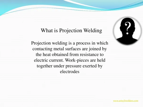
Definition Definition of Projection Welding • A resistance welding process that produces coalescence by the heat obtained from the resistance to the flow of the welding current. The resulting welds are localized at predetermined points by projections, embossments, or intersections. workpieces Moving Fixed transformer Projection welding setup.
Process Fundamentals Process Fundamentals • Two parts, one projected, are placed upon one another between two electrodes. • They make contact at the projected point. • High current starts to flow through projection. • Force is applied to cause the heated projection to collapse, and help fusion. B. A. Formation of a projection weld.
Introduction to Projection Welding (a) (b) (c) (d) [Reference: Welding Handbook, Volume 2, p.566, AWS]
Examples of Various Projection Designs (a) (b) (c) (d) (e) [Reference: Welding Handbook, Volume 2, p.562, AWS]
Examples of Various Projection Designs (CONT.) (f) (g) (h) (i) (j) [Reference: Welding Handbook, Volume 2, p.562, AWS]
Projection Design Projection Design Projection should be • sufficiently rigid to support the electrode force. • have adequate mass to heat a spot. • collapse without metal expulsion. • be easy to form. • cause little distortion to the part. Spherical radius D Projection should blend into stock surface without shouldering Wall thickness should be at least 70% of sheet thickness General design of a projection steel sheet
Advantages of Projection Welding • A number of welds can be made simultaneously in one welding cycle of the machine • Less overlap and closer weld spacings are possible • 1 < Thickness ratio < 6 • Smaller in size than spot welding • Better appearance on the side without projection • Less electrode wear than spot welding • Oil, rust, scale, and coatings are less of a problem than spot welding
Limitations of Projection Welding • Require an additional operation to form projections • With multiple welds, require accurate control of projection height and precise alignment of the welding dies • Thickness limitation for sheet metals • Require higher capacity equipment than spot welding
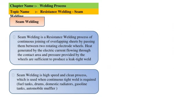
Definition of Seam Welding Resistance Seam Welding (RSEW): A resistance welding process which produces coalescence at the faying surface by heat obtained from resistance to electric current through the work parts held together under pressure by electrodes. The resulting weld is a series of overlapping resistance spot welds made progressively along a joint by rotating the electrodes.
Introduction to Resistance Seam Welding Roll Spot Weld Upper Electrode Wheel Knurl or Friction Drive Wheel Overlapping Seam Weld Continuous Seam Weld Workpiece Throat [Reference: Welding Handbook, Volume 2, p.553, AWS] Lower Electrode Wheel
Lap Seam Weld Overlapping Weld Nuggets Electrodes Travel Front view Side View [Reference: Welding Handbook, Volume 2, p.554, AWS]
Mash Seam Weld Slightly Lapped Sheets Wide, Flat Electrodes Weld Nuggets Before welding After Welding [Reference: Welding Handbook, Volume 2, p.554, AWS]
Metal Finish Seam Weld Finish Side Chamfered Electrode Flash Broad, Flat Electrode Before Welding After Welding [Reference: Welding Handbook, Volume 2, p.554, AWS]
Definition of Flash Welding • A resistance welding process in which coalescence is produced simultaneously over the entire abutting surfaces.
Flash Welding Process • Two parts to be joined are clamped in dies. • The dies are connected to a transformer. • A voltage is applied as one part approaches other. A. Position and clamp the parts. B. Apply flashing voltage
C. Flash D. Upset and terminate current Flash Welding Process • Upon contact, resistive heating occurs. • High amperage causes rapid melting and explosion of the metal known as flashing. • Finally an upsetting force is applied to forge the parts together.
Movable platen Fixed platen Transformer Cross section after welding Flash Welding Common Types Of Flash Welds Axially aligned weld. Meter weld
Common Types of Flash Welds Movable platen Fixed platen X-section after welding Transformer Ring weld
Flash Welding Applications • Wheel rims in the automotive industry • Motor and generator frames in the electrical industry. • Landing gear, control assemblies and hollow propeller blades in the aircraft industry. • Typical metals used are stainless steel, aluminum, copper, and nickel alloys.
Introduction to Upset Welding To Welding Transformer Clamping Die Clamping Die Heated Zone Upsetting Force Movable Part Stationary Part Finished Upset Weld [Reference: Welding Handbook, Volume 2, p.598, AWS]
Resistance Butt Welded Spike for a Baseball Shoe Abrasion-Resistant Cemented Tungsten Carbide Tip Resistance Butt Welded to Carbon Steel Sole Attachment Ogawa, M et al, “Spike For Baseball Shoe” US Patent 6,041,461 Mar 28, 2000
High Frequency Welding Applications Induction Coil HF HF HF Tube Butt Seam Tube Butt Seam Tube Mash Seam [Reference: Welding Handbook, Volume 2, p.653, AWS]
High Frequency Welding Applications (CONT.) HF HF Strip Butt T-Joint HF HF Spiral Tube Fin Spiral Tube [Reference: Welding Handbook, Volume 2, p.653, AWS]
High Frequency Welding Applications (CONT.) HF Induction Coil Projection Seam HF HF Bar Butt Pipe Butt [Reference: Welding Handbook, Volume 2, p.653, AWS]
Advantages of High-Frequency Welding • Produce welds with very narrow heat-affected zones • High welding speed and low-power consumption • Able to weld very thin wall tubes • Adaptable to many metals • Minimize oxidation and discoloration as well as distortion • High efficiency
Limitations of High-Frequency Welding • Special care must be taken to avoid radiation interference in the plant’s vicinity • Uneconomical for products required in small quantities • Need the proper fit-up • Hazards of high-frequency current
Some Products of High-Frequency Welding [Reference: Welding Handbook, Volume 2, p.665, AWS]
Percussion Welding (PEW): A resistance welding process which produces coalescence of the abutting members using heat from an arc produced by a rapid discharge of electrical energy. Pressure is applied percussively during or immediately following the electrical discharge.
Resistance Brazing Resistance Brazing/Soldering (RB): A brazing/soldering process in which the heat required is obtained from the resistance to electric current in a circuit of which the work is a part.
Electro-brazing W. Stanley, Resistance Welding McGraw-Hill, 1950
Resistance Soldering Flexible Braided Buss to Automotive Rear Window Braided Wire Glass Contact Pad With Ball of Solder Silver Ceramic Rear Window with Silver Ceramic Material Silk Screened onto Surface Flat Braided Wire with Contact Pad Attached Current Passed, Melts Solder, Bond Made Ingles, G et al “Braided Buss Bar with Selectively Clad Solder Pad Attachments” US Patent 6,042,932 Mar 28, 2000