Download
1 / 20
200 likes | 295 Views
spoiler. Collimator Wakefield Issues. Outline Introduction Wake potentials Measurements Project Plan Conclusions. Nigel Watson CCLRC – RAL/PPD. Introduction. Success of LC requires High (integrated) luminosity Acceptable backgrounds Machine protection

E N D
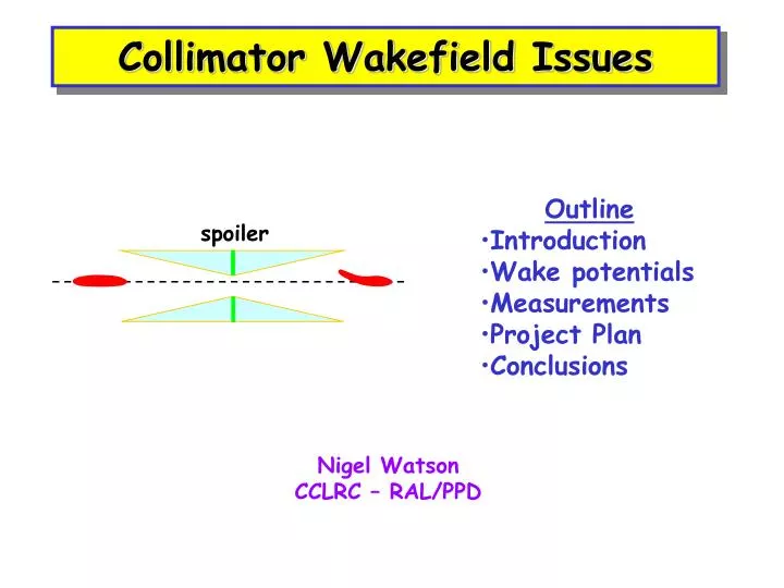
spoiler Collimator Wakefield Issues • Outline • Introduction • Wake potentials • Measurements • Project Plan • Conclusions Nigel Watson CCLRC – RAL/PPD
Introduction • Success of LC requires • High (integrated) luminosity • Acceptable backgrounds • Machine protection • Detectors must be able to turn on and use recorded data • High luminosity • Minimise emittance growth, DR IP • Control relative beam-beam motion at IP • High beam currents Nigel Watson/CCLRC-RAL
spoiler absorber 1mm Spoiler/Absorber • Thin (<1X0) spoilers • spread out beam, multiple Coulomb scattering, dE/dx • Low z bulk, but require durable, low resistivity surface • Damaged surfaces significant effect on WF behaviour • Thick (20-30X0) absorbers, in spoiler shadow SLC, 20mm Au coating on Ti [Decker et al, Linac’96] Nigel Watson/CCLRC-RAL
Collimator Wakefields • Conservative system design, to remove ~ 0.1% of beam • Avoid large amplitude component from entering FF • Mechanical collimators close to beam • Continuously scrape halo (~10kW) • Enlarge spot size of mis-steered beam by Coulomb scattering • Beam excites wake potential in material, acts back on (tail of) bunch: • Transverse loss (“kick”) factor, y’=Ky (near axis) • Position jitter angle jitter • Jitter amplification a la TRC: Ab=Kb; p(1+Ab2)1/2 • Emittance growth De/e A2b Nigel Watson/CCLRC-RAL
Jitter Amplification Comparison De/e A2b • Vertical plane, unacceptablejitter • NB: with tail folding OFF, pessimistic/conservative • Tail folding loosens collimation requirements • Reduces significance of collim. wake fields • Experimental verification? Nigel Watson/CCLRC-RAL
Collimator Wakefields • WF in vertical plane important even in error free machine • Collim at betatron phase of FD most criticaL • Contribute to position jitter of beam at IP • Separate into: to reduce effect use: • Geometric wake smooth tapers • Resistive wall wake high conductivity • Roughness impedance high quality finish • Very difficult to calculate analytically - possible only for simple configurations • Difficult to model, esp. for short bunches (sz~300mm), shallow tapers (a~20mrad), small ½ gaps (b~0.4mm), in reasonable time Nigel Watson/CCLRC-RAL
Data • Recent measurements using dedicated facility at SLAC, study geometric and resistive wakes • Improvements to theory (Stupakov et al) • Geometric wakes for tapered, rectangular collimators • inductive (shallow tapers) • intermediate regime • diffractive (steep tapers) • Resistive wakes (Piwinski et al) • Analytic calculations used in TRC, assuming • is = Cu • no tail folding • near-axis wakes (linear, dipole region) • Near-wall wakes (non-linear) possible machine protection issue Nigel Watson/CCLRC-RAL
SLAC CollWake Expt. 1500mm At 1.19 GeV point in SLAC linac sz ~ 650mm Magnet mover, y range = 1.4mm, precision = 1mm Nigel Watson/CCLRC-RAL
Near wall wakes • Primarily study near axis wakes, dipole mode, ~linear region • Add bump, study near wall region • Non-linear, more important for machine protection Kick angle (mrad) Beam-collim. offset (mm) [From Tenenbaum, SLAC accel. seminar, Feb. ‘01] Nigel Watson/CCLRC-RAL
e.g. Resistive Wake Study • Initial study was of geometric wake • Second study compared Cu and graphite, same geometry • Reasonable agreement with resistive wake theory Kick angle (mrad) Beam-collim. offset (mm) [From Onoprienko, Seidel, Tenenbaum, EPAC’02] Nigel Watson/CCLRC-RAL
Third Set of Collimators • Continue study of resistive wakes, compare Cu vs. Ti • Thereafter, concentrate on geometric (+perhaps two-step) tapers Nigel Watson/CCLRC-RAL
Wakefield Reduction Methods • Optimisation of collimator form – need reliable/validated predictions • Ideal case - infinite long taper, circular • Realistic - include constraints from finite size, available longitudinal space, and adjustability • 2-step tapers • More complex shapes, non-linear tapers, … • Tail folding • (and if all else fails) increase vxd radius at IP? Nigel Watson/CCLRC-RAL
Project Plan • Studying basic physics effects • Not critically dependent on technology, but easier for cold machine • Aim to design optimal spoiler jaw (material/geometry) • Direct measurement of wakefields at SLAC • Dedicated facility, single beam measurements • Already one good collab. (Seidel/DESY) with Tenenbaum et al on graphite collimators • Also previous UK involvement (Brunel) • Progress slow – need two interventions + technical experts to install new collimators, plus operation time • Turn around ~ 1 set of 4 spoiler jaws per 1.5yr (3 between ’99-04) • SLAC willing to collaborate, situation evolving post ITRP decision Nigel Watson/CCLRC-RAL
Project Plan • Design/test optimal spoiler jaw profiles (material/geometry) • Beam tests slow, need improved turnround to test new ideas • RGC.’s proposal (8/03) to use cold tests, building on group’s expertise and existing h/w at DL/Lancaster • Emulate beam by short pulse along thin wire stretched along axis of pipe with spoilers inside • Microwave signal excites h.o. modes, then measure: • Distortion of current pulse on leaving structure in time domain • Transmission parameter S21 as f(freq.) • Integration of impedances -> loss factors • Study variation with displacement of wire from axis • Challenging, but benefits from strong collaboration within CI (CCLRC/Lancaster) Nigel Watson/CCLRC-RAL
Project Plan • Set up cold test rig within CI (calibration, etc.) • SLAC recently using coaxial wire in freq. domain, measure loss factors in NLC accelerating structures (Baboi, Jones et al) • Do-able! • Benchmark against known spoiler profile, large taper angle, MAFIA etc. simulation • Carl has started to set up MAFIA simulations • Extend to alternative designs (e.g. multi-step or non-linear tapers), extract at least relative performance • Use cold test results to: • Provide data to assist development of improved e.m. modelling in problematic regimes • Also within UK, build up expertise (non-LC applications) • (Within EUROTeV) collaborate with TU Darmstadt • Design one-off test proposal for direct beam measurement at SLAC • With FP6 funding, extend into material damage studies Nigel Watson/CCLRC-RAL
TDR impedance measurements • Used for SRS components • SRS bunch length at injection ~ 20ps • Fast step pulse gaussian via IFN, into vessel • Receive pulse on sample ‘scope, waveform analysis gives loss parameter [From Hill&Pugh, EPAC’94] Nigel Watson/CCLRC-RAL
TDR setup ~1.7m • Carl B. examined mothballed h/w • Many conical launch cones (need rectangular) • Thin wire (250mm?) • Consider vertical plane operation to avoid sag • Critical issue: • Pulse speed! • Time ~ LC bunch sz • ~1 ps • Quick survey, fastest available “off the shelf” pulse generator for TDR ~ 10ps (Tek. 80E04 module+PSPL module+ TDS8200 scope) • Options: • build our own fast rise source • scale up spoilers (but x10?!) • alternative approaches? • Lancaster freq. domain h/w? [From Hill&Pugh, EPAC’94] Nigel Watson/CCLRC-RAL
SLAC • Considering move of WF box to End Station A • Significant improvement in access, share time with Mike Woods tests in ESA • Access could allow ~2 sets profiles/yr • PT’s initial estimates, kick resolution comparable to sector 2 location, even with higher beam energy • Better single pulse resolution • Longer lever arms for BPMs • Timescale not fixed, but assuming no disasters crop up, expect to be done in current (US) FY • Will help us, but does not remove need for cold tests Nigel Watson/CCLRC-RAL
Improved Predictions [Yokoya formula] • Theoretical/Modelling • Zagorodnov, Weiland: ECHO • Uniformly Stable Conformal approach – very close to stable absolute error, ~ % • ~ indep. of collim. length • Even in region close to origin • Applicable for non-linear, near-wall wakes. • Essential improvements, permit more reliable optimisation transverse wake Nigel Watson/CCLRC-RAL
Summary&Conclusion • Understanding wakefields important for LC • Calculations (Bane, Stupakov) and modelling (esp. near wall) much improved, e.g. • ~constant (absolute) error, ~indep. of mesh – ECHO (Weiland, Zagorodnov) • More data will improve further • More reliable LC spoiler design • UK effort (Lancaster/CCLRC), starting programme of • cold tests • e.m. modelling • beam test • More ideas Build up UK expertise Nigel Watson/CCLRC-RAL