Download
1 / 37
370 likes | 543 Views
The Mu2e Experiment at Fermilab. Jim Miller Boston University for the Mu2e Collaboration June 6, 2008. Mu2e Collaboration. R.M. Carey, K.R. Lynch, J.P. Miller*, B.L. Roberts Boston University Y. Semertzidis, P. Yamin Brookhaven National Laboratory Yu.G. Kolomensky

E N D
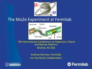
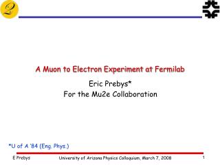
The Mu2e Experiment at Fermilab Jim Miller Boston University for the Mu2e Collaboration June 6, 2008
Mu2e Collaboration • R.M. Carey, K.R. Lynch, J.P. Miller*, B.L. Roberts • Boston University • Y. Semertzidis, P. Yamin • Brookhaven National Laboratory • Yu.G. Kolomensky • University of California, Berkeley • C.M. Ankenbrandt , R.H. Bernstein*, D. Bogert, S.J. Brice, D.R. Broemmelsiek,D.F. DeJongh, S. Geer, • M.A. Martens, D.V. Neuffer, M. Popovic, E.J. Prebys, R.E. Ray, H.B. White, K. Yonehara, C.Y. Yoshikawa • Fermi National Accelerator Laboratory • D. Dale, K.J. Keeter, J.L. Popp, E. Tatar • Idaho State University • P.T. Debevec, D.W. Hertzog, P. Kammel • University of Illinois, Urbana-Champaign • V. Lobashev • Institute for Nuclear Research, Moscow, Russia • D.M. Kawall, K.S. Kumar • University of Massachusetts, Amherst • R.J. Abrams, M.A.C. Cummings, R.P. Johnson, S.A. Kahn, • S.A. Korenev, T.J. Roberts, R.C. Sah • Muons, Inc. • R.S. Holmes, P.A. Souder • Syracuse University • M.A. Bychkov, E.C. Dukes, E. Frlez, R.J. Hirosky, A.J. Norman, K.D. Paschke, D. Pocanic • University of Virginia 50 Scientists 11 Institutes Recent LOI for Stage I measurement favorably reviewed by the Fermilab PAC
What is the measurement? Detect charged lepton flavor non-conservation in the coherent, neutrinoless conversion of a muon to an electron in the field of a nucleus: Measure the ratio of conversion relative to ordinary muon capture on the nucleus: (where ‘X’=(A, Z-1); or (A’,Z’)+ protons, neutrons, gammas) Current limits: R<4.3x10⁻¹² (Ti), R<7x10-13 (Au) (SINDRUM II at PSI) Goals of Mu2e: Stage I: R<6x10-17 (Al, 90% c.l.). An improvement over existing limit by four orders of magnitude! Stage II: (Project X) R<10-18 (Al).
Beyond the Standard Model • Charged Lepton Flavor Violation (CLFV) is a nearly universal feature of extensions to the Standard Model, and the fact that it has not yet been observed already places strong constraints on these models. • CLFV is a powerful probe of multi-TeV scale dynamics: complementary and in some cases more powerful than direct collider searches • Among various possible CLFV modes, rare muon processes offer the best combination of new physics reach and experimental sensitivity. • Muon to electron conversion • offers ultimate in LFV sensitivity because of experimental advantages over other reactions • Detection of muon to electron conversion is an unmistakable signal of new physics
The Method Muon beam line: Low energy pions decay to low energy muons Muon stops in an appropriate target, quickly forming a muonic atom with muon in 1s state Bohr radius (1s) much less than 1s orbit of innermost atomic electrons Bohr energy (1s) which is ~470 keV for Al 3 muon interactions can occur Muon to electron conversion Conversion electron is monoenergetic muon can decay Endpoint of bound muon same as conversion energy: muon can capture on nucleus For muonic Aluminum, muon lifetime is 0.86 ms; partial decay lifetime=2.2 ms, partial capture lifetime=1.5 ms
Some potential backgrounds Electrons from decay of muon bound in atomic orbit: max energy is same as conversion electron energy Probability falls rapidly near endpoint, This background can be separated from conversion electrons with good electron energy resolution: Require <1 MeV FWHM for Mu2e, R<6x10-17 Vast majority of decay electrons are < 53 MeV, well below conversion electron energy- big experimental advantage over This is an example of a ‘Delayed’ background Radiativepion capture, followed by photon conversion , Eg up to 140 MeV This is an example of a ‘Prompt’ background Possibility of ~105 MeV conversion electrons strong suppression of pionsis required Flux of low energy protons, neutrons, gammas from ordinary muon capture on stopping target nuclei- can lead to tracking errors. Beam electrons ~105 MeV Cosmic rays- suppress with shielding and 4p veto
SINDRUM II Experimental Method Low energy beamlinecollects muons from pion decay; beam line length is large enough so that most pions decay Pass beam through material to degrade energy: range out pions, muons continue on to stop in target Use a scintillator to detect charged particles entering stopping target. Detect electrons delayed relative to incident particle- Conversion electrons + background from muon interactions Reject prompt electrons- could be from beam pradiative capture or beam electron ‘One-at-a-time’ method limits rates to ~107/s: It would take ~ 100 years to get the statistics necessary to approach Mu2e goal of R<10-16
Previous muon decay/conversion limits (90% C.L.) m->e Conversion: Sindrum II LFV m Decay: High energy tail of coherent Decay-in-orbit (DIO) After background suppression, there are no counts in the region of interest. • Rate limited by need to veto prompt backgrounds! 8
The New Approach Based on the proposed MELC and MECO approach Go to a temporally narrow pulsed primary proton beam. Delay beginning of measurement period after proton injection pulse until almost all pions have decayed and other beam particles have dissipated (after about 700 ns). Establish high level of between-burst beam suppression (extinction ~10-9) to avoid p or e production leading to false conversion electrons during the measurement period. Select a stopping target having a muon lifetime which is matched to this delay time (Aluminum is a good choice: lifetime = 0.86 ms). Beam pulse spacing of ~1.7 ms is a good match for Al: collect data from .7-1.7 ms after muon injection pulse Ideally, there would be a continuous stream of muon pulses, ~100% duty factor
Muon Stopping Target Calorimeter Tracker Target Shielding Muon Beam Collimators Proton Target Pions Electrons Muons Detector Solenoid Transport Solenoid Production Solenoid Mu2e Muon Beamline Simulations with G4beamline (Code developed by Muons Inc)
Pions Proton Target Target Shielding (Copper) Protons enter here B=5T Target Shielding (Tungsten) Muons B=2.5T Proton Target and Superconducting Production Solenoid
Collimator 3 (Copper) Collimator 3 (Copper) - + (Showing muons only) Transport Solenoid
Calorimeter Tracker Muon Stopping Target B=1T 105 MeV/c Electrons B=1T B=2T Muons B=2 T Detector Solenoid
Stopping Target and Detectors Solenoid, 1m radius, B=2 T-> 1T from 0 to 4 m, B=1 T from 4 to 10 m Negative field gradient at targetcreates mirror increasing detector acceptance. Stopping target: thin to reduce energy loss and loss of energy resolution Tracker measures momentum of electrons to <1MeV FWHM: 2.6 m long, 0.5 cm Copious low energy charged particles (e.g. electrons from in-orbit muon decays) spiral down the hollow axis of the tracker, missing it entirely. Calorimeter after the tracker: provides fast trigger, confirms energy and position information on tracks.
Delivering Protons: “Boomerang” Scheme MI-8 -> Recycler done for NOvA Recycler(Main Injector Tunnel) New switch magnet extraction to P150 (no need for kicker) • Deliver beam to Accumulator/Debuncher enclosure with minimal beam line modifications and minimal civil construction. • Use Booster batches which would not otherwise be used for NoVA 15
Time Scale • Stage I, Booster-era, ~20-25 kW proton beam • MECO proposal is baseline design, vetted in several reviews • Readiness determined primarily by the four to five years to construct the solenoidal beam line after funding is available • Commissioning + data collection, ~3-4 years • LOI in Fall 2007, strong physics stamp of approval from PAC • Full proposal being prepared now for Fall 2008 PAC • Plan for a reasonable upgrade path to Stage II • Stage II, Project X, 200 kW proton beam, R<10-18 • Depends on Project X schedule and lessons learned in Stage I • Extensive upgrade studies will be needed: • Primary target upgrade to handle increased heat load • Production solenoid upgrade to handle increased heat and radiation loads on superconducting magnet. • Improved extinction • Improved detector to handle higher rates with improved energy resolution
Tasks • Tracker: two candidates, need R&D (simulations, prototypes) to choose • Calorimeter: Lead tungstate is baseline- limited initial prototype work- need to evaluate new crystal materials, new photo-sensitive devices • Cosmic ray veto system- candidate system has been proposed- needs to be developed- a challenge to get to 99.9% efficiency, 4p coverage • Simulations: • Have GEANT3, working; full GEANT4 simulation being developed, > manpower • Beam line optimization, background studies • Calibration systems for all detectors • Extinction monitor(p beam)- ideas exist- needs to be developed and built • Muon stopping rate monitor- Measure xray rate from muonic aluminum • Solenoid magnets (big project): joint effort of physicists and engineers. Initial design work done, needs further development for full design. • Develop readout electronics for calorimeter, tracker, cosmic veto,… • Identify a viable upgrade path to get to R<10-18 with Project X. • Develop the proton source, with needed extinction • …radiation shielding, building siting,… • If you might be interested in working on some of these tasks, let’s talk! Contact persons: Jim Miller: miller@bu.edu Bob Bernstein: rhbob@fnal.gov
Conclusions Muon to electron conversion is a powerful probe of new physics, complementary to LHC A baseline design exists on paper. It needs to be updated and holes filled in. Need prototypes; much development work remains P5 has given a strong endorsement, and FNAL is gearing up to do this experiment.
Example Sensitivities* Supersymmetry Compositeness Predictions at 10-15 Second Higgs doublet Heavy Neutrinos Heavy Z’, Anomalous Z coupling Leptoquarks *After W. Marciano
High Flux Muon Beam Following the idea from the MELC and MECO proposals, use a negative gradient solenoid, 5 T to 2.5 T, around the production target to mirror upstream-going low energy pions and muons back downstream into the beam line. Negative gradient causes p(longtudinal) to increase as particle moves downstream Use an ‘S’ shaped solenoid to transport the beam to the aluminum stopping target Avoids line-of-sight between detectors and production target: eliminate neutral bkg. Curved (toroidal) solenoid sections move beam vertically depending on charge and momentum: select low energy negative particles, attenuate everything else. Rates- Booster Era: 8 GeV protons, 23 kW average current, 4x10¹⁰ stopped muons/s, (Project X: 10 times more beam)
? ? ? me Conversion vs. meg • We can parameterize the relative strength of the dipole and four fermi interactions. • This is useful for comparing relative rates for mNeN and meg Courtesy: A. de Gouvea MEG proposal Sindrum II MEGA 34
History of Lepton Flavor Violation Searches 1 K0+e- K+++e- 10-2 - N e-N + e+ + e+ e+ e- 10-4 10-6 10-8 10-10 SINDRUM II 10-12 Initial MEG Goal 10-14 Initial mu2e Goal 10-16 10-16 19401950 1960 1970 1980 1990 2000 2010
Previous muon decay/conversion limits (90% C.L.) m->e Conversion: Sindrum II LFV m Decay: High energy tail of coherent Decay-in-orbit (DIO) • Rate limited by need to veto prompt backgrounds! 36
Sensitivity (cont’d) SU(5) GUT Supersymmetry: << 1 Littlest Higgs: 1 Randall-Sundrum: 1 R(mTieTi) R(mTieTi) • Examples with k>>1 (no meg signal): • Leptoquarks • Z-prime • Compositeness • Heavy neutrino 10-10 MEG 10-10 10-12 10-12 10-14 10-14 10-16 10-16 mu2e 10-9 10-11 10-11 10-15 10-13 10-13 Br(meg) Br(meg) 37