Download
1 / 24
270 likes | 424 Views
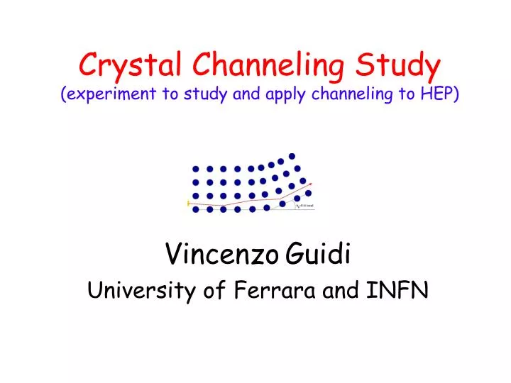
Crystal Channeling Study (experiment to study and apply channeling to HEP). Vincenzo Guidi University of Ferrara and INFN. Channeling in crystals. Trapping of charged particles in the inter-planar potential well (20 eV in Si). Critical angle.

E N D
Crystal Channeling Study(experiment to study and apply channeling to HEP) VincenzoGuidi University of Ferrara and INFN
Channeling in crystals Trapping of charged particles in the inter-planar potential well (20 eV in Si) Critical angle A bent crystal can be used to steer particles through channeling
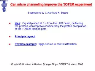
Applications to HEP • Halo cleaning in the LHC • Diffractive physics (TOTEM experiment) • In-situ calibration of the calorimeters in LHC experiments
Two-stagecollimation The number of secondary collimators grows quickly when background or machine protection requirements are strict and a high collimation efficiency is required.
Crystalcollimation Use a bent crystal to channel halo away from the beam core, intercept with a scraper downstream. Number of secondary collimators can be greatly reduced.
Optimal design for the LHC Optimal size of the silicon crystal for collimation is about 10 mm for 0.1 mrad (7 TeV). NIM B 234 (2005) 23
The RD-22 experiment • Large channelling efficiency measured for the first time in extraction mode • Consistent with simulation expectation for high energy beams • Experimental proof of multi-turn effect (channelling after multi-traversals) • Definition of a reliable procedure to measure the channelling efficiency The RD22 Collaboration, CERN DRDC 94-11
Intas projects • Energy at 1.3-70 GeV • Intensity 1012 protons in spills of 2 s duration • Efficiency greater than 85% • Equivalent to 1000 T dipole magnetic field Extraction efficiency vs. crystal length at 70 GeV PRL 87 (2001) 094802 PRL 90 (2003) 034801
Novel crystal configuration 0.5250 mm3 Bending exploits anticlastic effects due to anysotropy of crystalline Si
Novel crystal preparation • Dicing of the samples by a diamond-blade saw avoiding alignment with major crystalline axes. • Defects are induced by the dicing saw (a surface layer estimated to be as thick as 30m is rich in stratches, dislocations, line defects and anomalies). • Planar etching removes crystalline planes one by one RSI 73 (2002) 3170 Removal of such layer by wet planar etching (HF,HNO3,CH3COOH).
CRYSTAL S3 S4 EM S1 S2 VACUUM PIPE 7 meter Mechanical vs. chemical treatments Images of the beam deflected through mechanically treated (left) and chemically polished crystals (right)
NTA-HCCC project Chemical etching As diced As diced Chemical etching Chemical polishing enhances standard roughness (Ra)
Surfaceanalysis 30m APL87 (2005) 094102
Recentachievements (FNAL) FNAL results (2005) Crystal Collimator in E0 to replace a Tungsten Target
70 GeV p-beam Crystal 1 Magnets Collimator 5 m Crystal 2 S1 R=3 m 30 m Emulsion 1 Emulsion 2 S2 S3 Channeled_2 Channeled_1 35 m 4.6 m 1.3 m Background p-beam Recentachievements (IHEP)
Anomalous effects Exposure of emulsions 1 and 2 made at IHEP in 2002
U Channeled d Reflected Interpretation Particle reflection has been indicated as an interpretation for experimental evidences.
Incident Emulsion 1 • Emulsion 2 Channelled 6 C 5 4 B 3 Reflected 2 A 1 Interpretation First evidence for reflection in a crystal, theoretically predicted in Sov. J. Tech. 55 (1985) 1598
Reconsidering FNAL experiments 1 TeV Channeling at the Tevatron, October 5, 2005 Not volume capture, but volume reflection ! The observed tail beside the channeling peak is most likely induced by beam reflection into the crystal itself
CCS: an experiment to study and apply channeling to HEP • Continuous upgrading of performance of crystals boosted new achievements and new prospects. • Need for a newly conceived experiment to investigate novel phenomena. • Three-weeks machine time (external line H8, SPS) has been requested in 2006 and decision will be taken soon.
Basic idea of the experiment Bent beam 10 rad Line H8 - SPS Crystal Primary proton beam 100 rad Unbent beam 20 rad • 400 GeV/c • 105 p/spill • 5 mm in diameter • 3 rad divergence 10 rad Reflected beam The idea is to track the trajectoriesof the particles and to determine the cross sections for each branch
Layout of the experiment Goniometers with crystal holders Line H8 S2 S3 S1 vacuum vacuum p Si microstrips with 10 m resolution (AMS type) 1 m 34 m
Collaboration • CERN: infrastructure of the experiment • IHEP: lattice design, simulations (INTAS) • PNPI: crystals (INTAS) • JINR: simulation, DAQ (INTAS) • FNAL: mutual participation in experimental runs • FE: crystals, construction of the apparatus (CCS-NTA) • LNL: goniometers (CCS-NTA) • PG: Si microstrips (CCS) • Participation of persons from PI and TO
Details of the experiment CCS Duration: 3 years INFN personnel: FE (4 FTE), PG (2.5 FTE), LNL (4 FTE), TO, PI Cost in 2006: 150 kEuro for construction of detectors (AMS type) and implementation at CERN