Download
1 / 32
320 likes | 509 Views
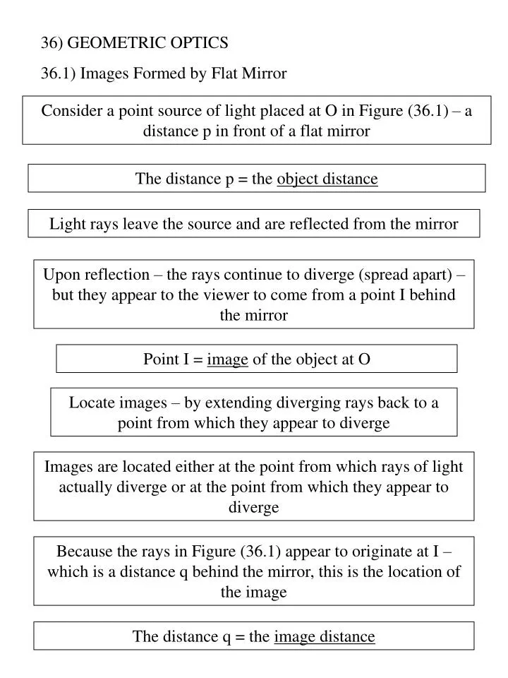
36) GEOMETRIC OPTICS 36.1) Images Formed by Flat Mirror. Consider a point source of light placed at O in Figure (36.1) – a distance p in front of a flat mirror. The distance p = the object distance. Light rays leave the source and are reflected from the mirror.

E N D
36) GEOMETRIC OPTICS 36.1) Images Formed by Flat Mirror Consider a point source of light placed at O in Figure (36.1) – a distance p in front of a flat mirror The distance p = the object distance Light rays leave the source and are reflected from the mirror Upon reflection – the rays continue to diverge (spread apart) – but they appear to the viewer to come from a point I behind the mirror Point I = image of the object at O Locate images – by extending diverging rays back to a point from which they appear to diverge Images are located either at the point from which rays of light actually diverge or at the point from which they appear to diverge Because the rays in Figure (36.1) appear to originate at I – which is a distance q behind the mirror, this is the location of the image The distance q = the image distance
Images Real Virtual Is formed when light rays pass through and diverge from the image point Is formed when the light rays do not pass through the image point but appear to diverge from that point Can be displayed on a screen (as at a movie) The image formed by the mirror in Figure (36.1) – the image of an object seen in a flat mirror is always virtual Cannot be displayed on a screen
Figure (36.2) – to examine the properties of the images formed by flat mirrors Need to follow only two light rays that leave the point on the object – to determine where an image is formed One of those rays starts at P – follows a horizontal path to the mirror, and reflects back on itself The second ray follows the oblique path PR and reflects as shown – law of reflection An observer in front of the mirror would trace the two reflected rays back to the point at which they appear to have originated, which is point P’ behind the mirror A continuation of this process for points other than P on the object would result in a virtual image (yellow arrow) behind the mirror Because triangles PQR and P’QR are congruent, PQ = P’Q Conclusion – the image formed by an object placed in front of a flat mirror is as far behind the mirror as the object is in front of the mirror
The object height h equals the image height h’ – lateral magnification M : (36.1) This is a general definition of the lateral magnification for anytype of mirror – for a flat mirror, M = 1 because h’ = h The image that is formed by a flat mirror has the folowing properties : The image has front-back reversal The image is as far behind the mirror as the object is in front of the mirror The image is unmagnified, virtual, and upright Example (36.2) : Multiple Images Formed by Two Mirrors Two flat mirrors are at right angles to each other (Figure (36.5)), and an object is placed at point O. In this situation, multiple images are formed. Locate the positions of these images
36.2) Images Formed by Spherical Mirrors Concave Mirrors Convex Mirrors Concave Mirrors Spherical mirror – has the shape of a section of a sphere Focuses incoming parallel rays to a point Figure (36.9a) – across-section of a spherical mirror – with its surface represented by the solid, curved black line Light is reflected from the inner, concave surface The mirror has a radius of curvature R, and its center of curvature is point C Point V is the center of the spherical section, and a line through C and V is called the principal axis of the mirror Figure (36.9)
Consider a point source of light placed at point O in Figure (36.9b) – where O is any point on the principal axis to the left of C Two diverging rays that originated at O are shown After reflecting from the mirror, these rays converge (come together) at the image point I They then continue to diverge from I as if an object were there As a result, we have at point I a real image of the light source at O Consider only rays that diverge from the object and make a small angle with the principal axis = paraxial rays All rays reflect through the image point (Figure (36.9b)) Rays that are far from the principal axis (Figure (36.10)) – converge to other points on the principal axis – blurred image = spherical aberration Figure (36.10)
Figure (36.11) To calculate the image distance q from a knowledge of the object distance p and radius of curvature R These distances are measured from point V Two rays leaving the tip of the object One of these rays passes through the center of curvature C of the mirror – hitting the mirror perpendicular to the mirror surface and reflecting back on it self The second ray strikes the mirror at its center (point V) and reflects – obeying the law of reflection The image of the tip of the arrow is located at the point where these two rays intersect From the gold right triangel (Figure (36.11)) : From the blue right triangle : The negative sign – the image is inverted, so h’ is negative The magnification of the mirror is : (36.2)
From the two triangles (Figure (36.11)), as one angle : and Find that : (36.3) Compare Equations (36.2) and (36.3) : Reduce to : Mirror equation in terms of R (36.4) Only to paraxial rays
If the object is very far from the mirror – if p is so much greater than R that p can be sais to approach infinity 1/p 0 Form Equation (36.4), q R/2 When the object is very far from the mirror – the image point is halfway between the center of curvature and the center point on the mirror – Figure (36.12a) The incoming rays from the object are essentially parallel – because the source is assume to be very far from the mirror The image point in this special case = focal point F The image distance = focal length f (36.5) Focal length Focal length is a parameter particular to a given mirror and therefore can be used to compare one mirror with another Figure (36.12) The mirror equation in terms of the focal length, f (36.6) Focal length – depends only on the curvature of the mirror, not on the material from which the mirror is made – because the formation of the image results from rays reflected from the surface of the material
Convex Mirrors Figure (36.13) – the formation of an image by a convex mirror – one silvered so that light is reflected from the outer, convex surface Diverging mirror – because the rays from any point on an object diverge after reflection as though they were coming from some point behind the mirror The image in Figure (36.13) is virtual – because the reflected rays only appear to originate at the image point – dashed line The image is always upright and smaller than the object Use in stores to foil shoplifters Use Equation (36.2), (36.4), and (36.6) – for either concave or convex mirrors Refer to the region in which light rays move toward the mirror as the front side of the mirror, and the other side as the back side Figure (36.10) and (36.12) – the side to the left of the mirrors is the front side, and the side to the right of the mirrors is the back side
Front, or real, side Back or virtual, side p and q positive p and q negative Incident light No light Reflected light Convex or concave mirror Figure (36.14) – state the sign conventions for object and image distance – refer Table (36.1) Figure (36.14)
Ray Diagrams for Mirrors To determine the positions and sizes of images formed by mirrors To draw the ray diagram, need to know : The position of the object The locations of the mirror’s focal point Center of curvature Figure (36.15) Draw three rays to locate the image These rays all start from the same object point and are drawn as follows : Ray 1 is drawn form the top of the object parallel to the principal axis and is reflected through the focal point F Ray 2 is drawn from the top of the object through the focal point and is reflected parallel to the principal axis Ray 3 is drawn from the top of the object through the center of curvature C and is reflected back on itself May choose any point on the object; for simplicity, choose the top of the object
The intersection of any two of these rays locates the image The third ray serves as a check of the construction The image point obtained in this fashion must always agree with the value of q calculated from the mirror equation What happens as the object is moved closer to the mirror – for concave mirrors Figure (36.15a) – the real, inverted image moves to the left as the object approaches the focal point When the object is at the focal point, the image is infinitely far to the left Figure (36.15b) - when the object lies between the focal point and the mirror surface – the image is virtual, upright, and enlarged – applies in the use of a shaving mirror or a makeup mirror, face is closer to the mirror than the focal point, see an upright, enlarged image of your face Figure (36.15c) – in a convex mirror, the image of an object is always virtual, upright, and reduced in size As the object distance increases, the virtual image dexreases in size and approaches the focal point as p approaches infinity Image position varies with object position
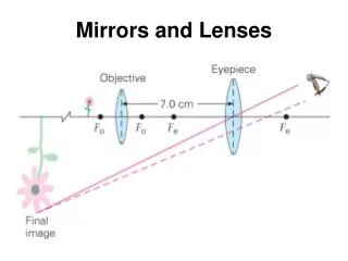
Example (36.4) : The Image from a Mirror Assume that a certain spherical mirror has a focal length of + 10.0 cm. Locate and describe the image for object distances of (a) 25.0 cm, (b) 10.0 cm, and (c) 5.00 cm. Example (36.5) : The Image from a Convex Mirror A woman who is 1.5 m tall is located 3.0 m from an antishoplifting mirror – Figure (36.16). The focal length of the mirror is - 0.25 m. Find (a) the position of her image and (b) the magnification. 36.3) Images Formed by Refraction Describe how images are formed when light rays are refracted at the boundary between two transparent materials Consider two transparent media having indices of refraction n1 and n2 , where the boundary between the two media is a spherical surface of radius R – Figure (36.17) Figure (36.17)
Assume that the object at O is in the medium for which the index of refraction is n1, where n1 < n2. Consider the paraxial rays leaving O All such rays are refracted at the spherical surface and focus at a single point I, the image point Figure (36.18) A singel ray leaving point O and focusing at point I Snell’s law of refraction applied to this refracted ray : Because 1 and 2 are assume to be small, use the small-angle approximation sin (radians) : An exterior angle of any triangel equals the sum of the two opposite interior angles – applying this rule to triangles OPC and PIC (Figure (36.18)) :
Combine all three expressions and eliminate 1 and 2 : (36.7) Three right triangles (Figure (36.18)) – have a common vertical leg of length d. For paraxial rays (unlike the relatively large-angle ray in Figure (36.18)) – the horizontal legs of these triangles are approximately p for the triangle containing angle , R for the triangle containing , and q for the triangle containing angle In the small-angle approximation, tan – the approximate relationships from these triangles : Substitute these expressions into Equation (36.7) and divide through by d to get : (36.8) For a fixed object distance p – the image distance q is independent of the angle that the ray makes with the axis – all paraxial rays focus at the same point I
Sign convention Define the side of the surface in which light rays originate as the front side The other sede is called the back side Real images are formed by refraction in back of the surface, in contrast with mirrors, where real images are form in front of the reflecting surface Because of the difference in location of real images – the refraction sigh conventions for q and R are opposite the reflection sign conventions Example : q and R are both positive in Figure (36.18) Table (36.2) – the sign conventions for spherical refracting surfaces Derived Equation (36.8) from an assumption that n1 < n2 – Equation (36.8) is valid regardless of which index of refraction is greater
Flat Refracting Surfaces • If a refracting surface is flat, then R is infinite and Equation (36.8) reduces to : (36.9) From this expression we see that the sign of q is opposite that of p Table (36.2) – the image formed by a flat refrcting surface is on the same side of the surface as the object
Figure (36.19) – the situation in which the object is in the medium of index n1 and n1 is greater than n2 A virtual image is formed between the object and the surface If n1 is less than n2 – the rays in the back side diverge from each other at lesser angles than those in Figure (36.19) As the result – the virtual image is formed to the left of the object Figure (36.19)
Example (36.8) : The One that Got Away A small fish is seimming at a depth d below the surface of a pond (Figure (36.21)). What is the apparent depth of the fish, as viewed from directly overhead ? Figure (36.21)
36.4) Thin Lenses Lenses – to form images by refraction in optical instruments : cameras, telescopes, and microscopes. Light passing through a lens experiences refraction at two surfaces The image formed by one refracting surface serves as the object for the sebond surface Thick lenses Consider a lens having an index of refraction n and two spherical surfaces with radii of curvature R1 and R2 – Figure (36.22) Figure (36.22) n1 = 1 n t
An object is placed at point O at a distance p1 in front of surface 1 If the object were far from surface1 – the light rays from the object that struck the surface would be almost parallel to each other. The refraction at the surface would focus these rays – forming a real image to the right of surface 1 – Figure (36.22)) If the object is placed close to surface 1 (Figure (36.22)) – the rays diverging from the object and striking the surface cover a wide range of angles and are not parallel to each other In this case – the refraction at the surface is not sufficient to cause the rays to converge on the right side of the surface. They still diverge – although they are closer to parallel than they were before they struck the surface. This results in a virtual image of the object at I1 to the left of the surface – Figure (36.22)) This image is then used as the object for surface 2 – results in a real image I2 to the right of the lens
Begin with the virtual image formed by surface 1 Using Equation (36.8) – assume n = 1 – the image I1 formed by surface 1 : (1) Where q1 is a negative number – a virtual image formed on the front side of surface 1 Apply Equation (36.8) to surface 2 – taking n1 = n and n2 = 1 Taking p2 as the object distance for surface 2 and q2 as the image distance : (2) The image formed by the first surface acts as the object for the second surface From Figure (36.22) p2 is the sum of q1 and t p2 = – q1 + t (t = thickness of the lens) q1 is a negative number and that p2 must be positive by the sign convention – a negative sign for q1
t is small compared to R For thin lens Neglect t Equation (2) becomes : (3) Adding Equations (1) and (3) : (4) For a thin lens – can omit the subscripts on p1 and q2 in Eq. (4) and call the object distance p and the image distance q – Figure (36.23) Eq. (4) becomes : (36.10) Relates the image distance q of the image formed by a thin lens to the object distance p and to the thin-lens properties (index of refraction and radii of curvature) Valid only for paraxial rays and only when the lens thickness is much less than R1 and R2
Figure (36.23) The focal length f of a thin lens is the image distance that corresponds to an infinite object distance - mirrors Letting p approach and q approach f in Eq. (36.10) – the inverse of the focal length for a thin lens is : Lens makers’ equation (36.11) If the lens is immersed in something other than air, this same equation can be used – with n interpreted as the ratio of the index of refraction of the lens material to that of the surrounding fluid
A biconvex lens (two convex surfaces – resulting in a converging lens) A biconcave lens (two concave surfaces – resulting in a diverging lens) From Eq. (36.11) : Thin-lens equation (36.12) Because light can travel in either direction through a lens – each lens has two focal points –– Figure (36.24) one for light rays passing through in one direction one for rays passing through in the other direction Focal point F1 =the object focal point, and F2 = the image focal point Figure (36.24)
Front Back p negative q positive p positive q negative Incident light Refracted light Figure (36.25)
Figure (36.26) Various lens shapes A converging lens is thicker at the center than at the edge A diverging lens is thinner at the center than at the edge Magnification of Images Consider a thin lens through which light rays from an object pass As with mirrors (Eq. (36.2) – the lateral magnification of the lens is defined as the ratio of the image height h’ to the object height h : When M is positive – the image is upright and on the same side of the lens as the object When M is negative – the image is inverted and on the side of the lens opposite the object
Ray Diagrams for Thin Lenses Ray diagrams For locating the images formed by thin lenses or systems of lenses Help clarify our sign conventions Figure (36.27a) and (36.27b) To locate the image of a converging lens Ray 1 is drawn parallel to the principal axis. After being refracted by the lens, this ray passes through the focal point on the back side of the lens Ray 2 is drawn through the center of the lens and continues in a straight line Ray 3 is drawn through that focal point on the front side of the lens (or as if coming from the focal point if p<f) and emerges from the lens parallel to the principal axis
Figure (36.27c) To locate the image of a diverging lens Ray 1 is drawn parallel to the principal axis. After being refracted by the lens, this ray emerges such that it appears to have passed through the focal point on the front side of the lens – dashed line Ray 2 is drawn through the center of the lens and continues in a straight line Ray 3 is drawn toward the focal point on the back side of the lens and emerges from the lens parallel to the optic axis Combination of Thin Lenses If two thin lenses are used to form an image (1) – the image formed by the first lens is located as if the second lens were not present (2) – a ray diagram is drawn for the second lens – with the image formed by the first lens now serving as the object for the second lens The second image formed is the final image of the system If the image formed by the first lens lies on the back side of the second lens – that image is treated as a virtual object for the second lens (p is negative)
Can be applied to a system of three or more lenses The overall magnification of a system of thin lenses equals the product of the magnifications of the separate lenses Special case – a system of two lenses in contact Two thin lenses of focal lengths f1 and f2 If p is the object distance for the combination – application of the thin-lens equation (Eq. (36.12)) to the first lens gives : q1 = the image distance for the first lens Treating this image as the object for the second lens – the object distance for the second lens must be – q1 (negative because the object is virtual) For the second lens : q= the final image distance from the second lens
Adding these equation – eliminates q1 : Focal length of two thin lenses in contact (36.13) Because the two thin lenses are touching, q is also the distance of the final image from the first lens Two thin lenses in contact with each other are equivalent to a single thin lens having a focal length given by Equation (36.13)