Download
1 / 24
240 likes | 492 Views
Rf Deflecting Cavity Design for Generating Ultra-short pulses at APS. Geoff Waldschmidt Radio Frequency Group Accelerator Systems Division Advanced Photon Source LHC IR Workshop, October 3, 2005. Feasibility study group*. RF K. Harkay D. Horan R. Kustom A. Nassiri G. Pile

E N D
Rf Deflecting Cavity Design for Generating Ultra-short pulses at APS Geoff Waldschmidt Radio Frequency Group Accelerator Systems Division Advanced Photon Source LHC IR Workshop, October 3, 2005
Feasibility study group* RF K. Harkay D. Horan R. Kustom A. Nassiri G. Pile G. Waldschmidt M. White Undulator radiation & x-ray optics L. Assoufid R. Dejus D. Mills S. Shastri Beam dynamics M. Borland Y.-C. Chae L. Emery W. Guo K.-J. Kim S. Milton V. Sajaev B. Yang A. Zholents, LBNL * All affiliated with APS except where noted G. Waldschmidt, APS RF Deflecting Cavity Design at APS LHC, 10/3/2005
Outline • Science case for storage ring ps pulses • Summary of beam and optics simulations and beam studies • Deflecting cavity designs • Room temperature vs. superconducting • Multi-cell and single-cell superconducting cavity designs • R&D plan • Summary G. Waldschmidt, APS RF Deflecting Cavity Design at APS LHC, 10/3/2005
Science Drivers for ps X-rays APS Strategic Planning Workshop (Aug 2004): Time Domain Science Using X-Ray Techniques “…by far, the most excitingelement of the workshop was exploring the possibility of shorter timescales at the APS, i.e., the generation of 1 ps x-ray pulses whilst retaining high-flux. This important time domain from 1 ps to 100 ps will provide a unique bridge for hard x-ray science between capabilities at current storage rings and future x-ray FELs.” Atomic and molecular dynamics, coherent/collective processes: • Atomic and molecular physics • Condensed matter physics • Biophysics/macromolecular crystallography • Chemistry APS User’s Meeting: Workshop on Generation and Use of Short X-ray Pulses at APS (May 2005) Slide Courtesy K. Harkay G. Waldschmidt, APS RF Deflecting Cavity Design at APS LHC, 10/3/2005
Atomic Ex. States Proton Transfer Period of Moon Bound Water Relaxation Ex. State Fe57 Cell Division Rotations Bond Breakage DNA Unfolding Protein Folding Phonon Frequency Lasers APS ps source X-ray Techniques Workshop on Time Domain Science Using X-ray Techniques D. Reiss, U. Michigan 106 104 102 100 10-2 10-4 10-6 10-8 10-10 10-12 10-14 10-16 Ultrasonic EPR NMR Storage Ring Sources X-ray FELs G. Waldschmidt, APS RF Deflecting Cavity Design at APS LHC, 10/3/2005
XFELs can provide • fs pulses • Ultrahigh peak power • Ultrahigh brightness • Lower avg. repetition rate • Storage rings can provide • ~1 ps pulses • Energy tunability • Spectral stability • Flux comparable to 100 ps • High repetition rate Storage Ring ps Sources Offer Unique Capability Note: Femtoslicing not practical at APS (calc per A. Zholents) Energy modulation DE=7se requires: ~10 mJ laser pulse at lL=400 nm and t=50 fs giving ~ 100 fs x-ray pulse with ~ 105 photons per pulse BUT: looks difficult at a high rep. rate G. Waldschmidt, APS RF Deflecting Cavity Design at APS LHC, 10/3/2005
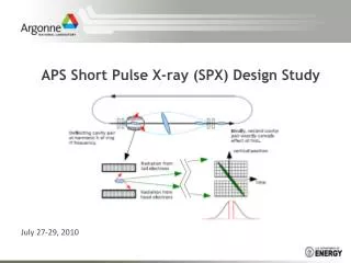
Δt Slitting alone or add compression using asymmetric cut crystal; throughput ~ 2-15x better Compressed pulse length (linear rf): Generation of ps Pulses Fig courtesy A. Nassiri For APS: h=8, 6 MV deflect. voltage, σy’,e = 2.2 μrad, and σy’,rad = 5 μrad; the calc’d compressed x-ray pulse length is ~0.36 ps rms. A. Nassiri G. Waldschmidt, APS RF Deflecting Cavity Design at APS LHC, 10/3/2005
Parameters / Constraints: What hV is Required? Can get the same compression as long as h*V is constant V=6, h=4 V=4, h=6 Higher V and lower h: more linear chirp and less need for slits V=6, h=8 Higher h and lower V: smaller maximum deflection and less lifetime impact Cavity design and rf source issues h=7, V<6 MV? Higher h and maximum V: shortest pulse, acceptable lifetime Beam dynamics simulation study: h ≥ 4 (1.4 GHz) V ≤ 6 MV (lifetime) M. Borland, APS ps Workshop, May 2005 G. Waldschmidt, APS RF Deflecting Cavity Design at APS LHC, 10/3/2005
X-ray Compression Optics Simulation(R. Dejus) Pulse histogram using optics compression and a slit of 8.0 mm (half-width). The rms width is 1.19 ps (FWHM ~ 2.8 ps), and the transmission is 62%. 2D scatter plot, undulator A irradiance at 30 m, 10 keV. Red = 10% level, green = 37% (1/e).; ~ 20% are thrown away. The tilt angle β is ~ 55°. G. Waldschmidt, APS RF Deflecting Cavity Design at APS LHC, 10/3/2005
Ultrashort X-ray Pulse Generation Test 1 Transient, short pulses are generated using an alternate scheme based on synchrobetatron coupling (suitable for study, but not operation). At left, an image of the beam 0.3 ms after a vertical kick, using APS sector 35 optical streak camera. At right, a short pulse is observed using a 40 μm vertical slit (fit gives 5.8 ps rms, nominal bunch length 30 ps). W. Guo, K. Harkay, B. Yang, M. Borland, V. Sajaev, Proc. 2005 PAC Carry out a demonstration short-pulse x-ray experiment on APS beamline Structural molecular reorganization following photoinduced isomerization/ dissociation can be studied on a finer timescale. Transient pulse requires acquisition of entire x-ray absorption spectrum in a single shot. (L. Young and colleagues) G. Waldschmidt, APS RF Deflecting Cavity Design at APS LHC, 10/3/2005
Room Temperature (RT) vs. Superconducting (SC) RF(K. Harkay, A. Nassiri) • No installed “crab cavity” in existing synchrotron facilities • Need to study and understand transients during pulsing of RT structure and its effect on SR beam. How does it affect “non-crab” beamline users? • RT pulsed system allows user to “turn off” ps pulse via timing (~1 s pulse, 0.1 – 1 kHz rep rate) (M. Borland, P. Anfinrud) • KEKB plans to install two SC single cell cavity in March 2006 • SC system runs CW, rep rate up to bunch spacing; some experiments desire high rep rate (no pump probes) (D. Reiss) • Either option requires dedicated R&D effort G. Waldschmidt, APS RF Deflecting Cavity Design at APS LHC, 10/3/2005
9 Cells SW Deflecting Structure V. Dolgashev, SLAC, APS seminar, June 2005 • Pulsed heating < 100 deg. C • BMAX < 200 kA/m for 5 μs pulse (surface) • Limited available power ≤ 5 MW • EMAX < 100 MV/m (surface) G. Waldschmidt, APS RF Deflecting Cavity Design at APS LHC, 10/3/2005
SC RF Cavity Study for APS (G. Waldschmidt, G. Pile, D. Horan, R. Kustom, A. Nassiri, K. Harkay) • Single-cell vs. multiple-cell SC cavity configurations • Orbit displacement causes beam loading in crabbing mode; adopt KEKB criterion of y = ±1 mm (for orbit distortions ± 0.1 mm) Superconducting Deflecting Cavity Design Parameters G. Waldschmidt, APS RF Deflecting Cavity Design at APS LHC, 10/3/2005
21.3 cm Squashed RF Crab Cavity Designs (based on KEK design) G. Waldschmidt, APS RF Deflecting Cavity Design at APS LHC, 10/3/2005
Dipole mode electric field Coaxial beam pipe damper Waveguide input coupler Single-Cell Deflecting Cavity: Coaxial Beam Pipe Damper • Multiple cells produce multiplicity of parasitic modes. Single-cell cavity chosen due to stringent HOM requirements. • Coaxial beam pipe damper (CBD) is located on one side of the cavity and extracts LOM’s and HOM’s from cavity • LOM / HOM’s can couple to the coaxial beam pipe as a TEM mode. HOM’s can also couple as higher order coaxial modes • HOMs above beam pipe cutoff, propagate along CBD and / or through other beam pipe G. Waldschmidt, APS RF Deflecting Cavity Design at APS LHC, 10/3/2005
Deflecting mode filter Waveguide to damper load Single-Cell Deflecting Cavity: Rejection Filter • Deflecting mode creates surface currents along the coaxial beam pipe damper, but does not propagate power. • When a resistive element is added, there is substantial coupling of power into the damping material. • A radial deflecting mode filter rejects at ~ -10 dB. • Performance improvement pursued as well as physical size reduction. G. Waldschmidt, APS RF Deflecting Cavity Design at APS LHC, 10/3/2005
Rejectionfilter Coaxialtransmissionline Coaxial transmission lines Excitationantenna Rejection filter not shown LOM Damping • Damping load is placed outside of cryomodule. • Ridge waveguide and coaxial transmission lines transport LOM / HOM to loads • Efficiency of deQing was simulated by creating the TM010 mode with an axial antenna. • Stability condition for LOM achieved when Q < 12,900 for 100 mA beam current. • Unloaded Q of LOM was 4.34e9. • Coaxial beam pipe damper with four coaxial transmission lines, damped the LOM to a loaded Q of 1130. G. Waldschmidt, APS RF Deflecting Cavity Design at APS LHC, 10/3/2005
Instability Thresholds from Parasitic Mode Excitation(per Y-C. Chae) APS parameters assumed: I= 100 mA, E = 7 GeV,a=2.8e-4, ws/2p=2 kHz,ns=0.0073,bx= 20 m [1] A. Mosnier, Proc 1999 PAC. [2] L. Palumbo, V.G. Vaccaro, M. Zobov, LNF-94/041 (P) (1994; also CERN 95-06, 331 (1995). G. Waldschmidt, APS RF Deflecting Cavity Design at APS LHC, 10/3/2005
Damping Parasitic Modes f < fc G. Waldschmidt, APS RF Deflecting Cavity Design at APS LHC, 10/3/2005
Space Requirements • Total available space at the APS for deflecting cavity assembly is 2.5 m. • Assuming ten single-cell cavities, and 0.4 m on each end for an ion pump/valves/bellow assembly, the total space required by the following physical arrangement is ~ 2.6 m. • Additional dampers may also be required. • Coupling between cavities must be addressed • Impedance bump in coaxial beam pipe damper or shorting plane may be used • Beam impedance considerations may require different cavity configuration G. Waldschmidt, APS RF Deflecting Cavity Design at APS LHC, 10/3/2005
Summary of RF Design Considerations • SC CW option is more attractive • May offer a greater degree of compatibility with normal SR operation • Compatible with future development of higher rep rate pump probe lasers • Opportunity for APS to gain SC rf expertise • Goal 1 ps in crab insertion • No impact of crab cavities on performance outside insertion • Availability of 100-kW class rf amplifiers limits study to h = 8 (2.8 GHz) • Available insertion length for cavities nominally 2.5 m (could be extended) • Effects of errors: emittance growth or orbit kicks (M. Borland) • Intercavity phase error < 0.04 for <y’>/σy’ < 10% • Intercavity voltage difference < 0.5% • Significant parasitic mode damping requirement (Y-C Chae) G. Waldschmidt, APS RF Deflecting Cavity Design at APS LHC, 10/3/2005
SC RF Issues to be Resolved • Physically realizable coaxial beampipe damper and optimized filter. • Extraction of power from parasitic modes • Removal of heat load outside of cryo-module. • Quantify power handling requirements • Additional dampers and/or enlarged beam pipe on input coupler side • Examination of inter-cavity coupling • Compare coaxial and waveguide input couplers for ease of implementation and HOM damping. • Cavity optimization • Tuner design • Beam impedance calculation • Evaluation of microphonics • 2.5 m space limitation !! G. Waldschmidt, APS RF Deflecting Cavity Design at APS LHC, 10/3/2005
R&D Draft Plan • Feasibility study completed • SC rf technology chosen • Model impedance effects (parasitic modes, head-tail) • Finalize RF system design, refine simulations • System review of crab cavities at KEKB during assembly and testing • Refine x-ray compression optics design, end-to-end ray tracing • Conduct proof of principle tests (beam dynamics, x-ray optics) • Chirp beam using synchrobetatron coupling (transient) (W. Guo) • Install 1 MV RT S-band structure, quarter betatron tune (M. Borland, W. Guo) • Install warm model of SC rf cavity (passive), parasitic mode damping (K. Harkay) G. Waldschmidt, APS RF Deflecting Cavity Design at APS LHC, 10/3/2005
Summary • We believe x-ray pulse lengths ≤ 1 ps achievable at APS • SC RF chosen as baseline after study of technology options • RF priorities include parasitic mode damping and cavity assembly optimization with physical length constraints • Beam impedance calculation may have appreciable effect on final design • Optics design performed in parallel with RF. Optics compression increases throughput 2-15x better than slits alone. • Proof of principle R&D is underway: beam/photon dynamics • Operational system possibly ≤ 3 yrs from project start G. Waldschmidt, APS RF Deflecting Cavity Design at APS LHC, 10/3/2005