Download
1 / 14
160 likes | 349 Views
ECE 551 - Digital System Design & Synthesis Lecture 9.0 - Design Partitioning for Synthesis. Strategies Partition for design reuse Keep related combinational logic together Avoid glue logic, particularly at top level Register block outputs Partition by design goal

E N D
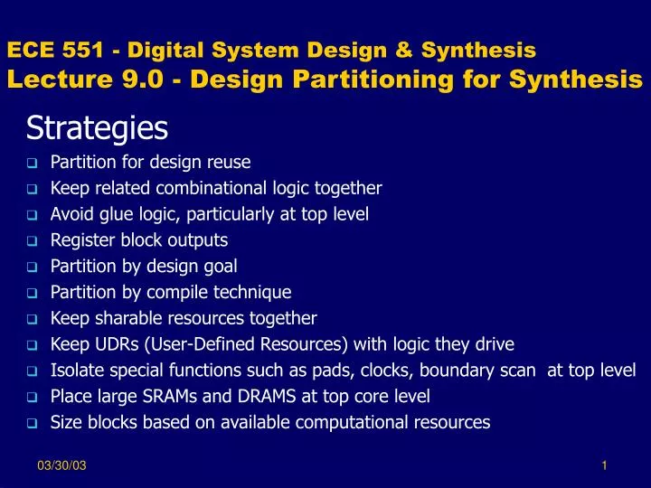
ECE 551 - Digital System Design & SynthesisLecture 9.0 - Design Partitioning for Synthesis Strategies • Partition for design reuse • Keep related combinational logic together • Avoid glue logic, particularly at top level • Register block outputs • Partition by design goal • Partition by compile technique • Keep sharable resources together • Keep UDRs (User-Defined Resources) with logic they drive • Isolate special functions such as pads, clocks, boundary scan at top level • Place large SRAMs and DRAMS at top core level • Size blocks based on available computational resources
References • Most from section 3 of Design Compiler User Guide (DCUG) • Others from project experience
Design Reuse • Partition so that existing designs can be used in your design • To permit future reuse: • Define and document interface thoroughly • Standardized interface • Parameterize the code
Keeping Related Combinational Logic Together • Reasons: • Default DC cannot move logic across hierarchical boundaries • Logic optimization cannot cross block boundaries • Group related combinational logic & destination register together • Improves logic optimization potential • Enables sequential optimization
Avoid Glue Logic • Glue Logic • Small amounts of logic added to correct interface mismatch or add missing functionality • Eliminating glue logic • Improves logic optimization potential • Reduces compile time • At top level, simplifies floor-planning
Register module outputs • If module outputs are not registered: • long, complex inter-module delay paths can exist • Example • Simulation speed is slower due to sensitivity lists that contain more than clock & reset • Example • Drive strengths on inputs to modules differ
Register module outputs (continued) • Negatives • Registering outputs may add clock periods to system delays for function execution • Registering outputs may severely restrict module boundary locations
Partition by Design Goal • Design Goals • Area minimization • Delay minimization • By partitioning on design goals: • Allows area constraints on logic without timing issues • Allows timing constraints on logic without area issues • Reduces optimization effort
Partition by Compile Technique • Compile Techniques • Forcing Structure (factoring) • Forcing Flattening (2-level logic) • Examples: • XOR-heavy error detection and correction Circuits should be structured • Random logic should be flattened • Therefore, should not be together in module
Keep Sharable Resources Together • Only resources within the same always can be shared.
Isolating Special Functions • Includes pads, I/O drivers, clock generation, boundary scan, and asynchronous modules • The external interface should be at the top level and not placed in modules • Special functions that tie to the interface should be at the next hierarchical level down • Asynchronous functions should be separate modules at an appropriate level of the hierarchy • Example: Figure 3-10 DCUG (See next slide)
Place large SRAMs, DRAMS & ROMs at top core level • Relates to physical design interaction with synthesis • Large memory structures need to be placed in the floorplan independently of logic • Floorplanning is needed to do accurate timing analysis and control • Example
Size blocks based on computational resources • Large blocks permit optimization flexibility • Large block may overwhelm workstation in terms of memory, swap space or processing throughput • Large blocks my cause excessive compile times • Thus, need to select workable intermediate size for blocks