Download
1 / 41
670 likes | 1.54k Views
LECTURE 6: INTRODUCTION TO HEAT EXCHANGER NETWORK SYNTHESIS. Schedule – Introduction to HEN Synthesis. Unit 1 . Introduction: Capital vs. Energy What is an optimal HEN design A Simple Example (Class Exercise 1) Setting Energy Targets Unit 2. The Pinch and MER Design

E N D
LECTURE 6: INTRODUCTION TO HEAT EXCHANGER NETWORK SYNTHESIS DESIGN AND ANALYSIS II - (c) Daniel R. Lewin
Schedule – Introduction to HEN Synthesis • Unit 1. Introduction: Capital vs. Energy • What is an optimal HEN design • A Simple Example (Class Exercise 1) • Setting Energy Targets • Unit 2. The Pinch and MER Design • The Heat Recovery Pinch • HEN Representation • Class Exercise 2 • Unit 3. The Problem Table • Class Exercises 3 and 4 DESIGN AND ANALYSIS II - (c) Daniel R. Lewin
Schedule – Advanced HEN Synthesis • Unit 4. Loops and Splits • Minimum Number of Units by Loop Breaking • Class Exercise 5 • Stream Split Designs • Class Exercise 6 • Unit 5. Threshold Problems • Class Exercise 7 DESIGN AND ANALYSIS II - (c) Daniel R. Lewin
Schedule – Heat and Power Integration • Unit 6. Data Extraction • Class Exercise 8 • Unit 7. Heat Integration in Design • Grand Composite Curve • Heat-integrated Distillation • Heat Engines • Heat Pumps DESIGN AND ANALYSIS II - (c) Daniel R. Lewin
Part One: Objectives • The first part of this three-part Unit on HEN synthesis serves as an introduction to the subject, and covers: • The “pinch” • The design of HEN to meet Maximum Energy Recovery (MER) targets • The use of the Problem Table to systematically compute MER targets • Instructional Objectives: • Given data on hot and cold streams, you should be able to: • Compute the pinch temperatures • Compute MER targets • Design a simple HEN to meet the MER targets DESIGN AND ANALYSIS II - (c) Daniel R. Lewin
UNIT 1: Introduction - Capital vs. Energy • The design of Heat Exchanger Networks deals with the following problem: • Given: • NH hot streams, with given heat capacity flowrate, each having to be cooled from supply temperature THS to targets THT. • NC cold streams, with given heat capacity flowrate, each having to be heated from supply temperature TCS to targets TCT. • Design: • An optimum network of heat exchangers, connecting between the hot and cold streams and between the streams and cold/hot utilities (furnace, hot-oil, steam, cooling water or refrigerant, depending on the required duty temperature). • What is optimal? • Implies a trade-off between CAPITAL COSTS (Cost of equipment) and ENERGY COSTS (Cost of utilities). DESIGN AND ANALYSIS II - (c) Daniel R. Lewin
Network for minimal energy cost ? Network for minimal equipment cost ? Example DESIGN AND ANALYSIS II - (c) Daniel R. Lewin
Design B: (AREA) = 13.3 Design A: (AREA) = 20.4 [ A = Q/UTlm ] Numerical Example DESIGN AND ANALYSIS II - (c) Daniel R. Lewin
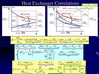
Some Definitions TS = Stream supply temperature (oC)TT = Stream target temperature (oC)H = Stream enthalpy (MW)CP = (MW/ oC) = Heat capacity flowrate (MW/ oC) = Stream flowratespecific heat capacity DESIGN AND ANALYSIS II - (c) Daniel R. Lewin
20o 30o 10o 20o DTmin - Example Tmin = Lowest permissible temperature difference Which of the two counter-current heat exchangers illustrated below violates T 20 oF (i.e. Tmin = 20 oF) ? Clearly, exchanger A violates the Tmin constraint. DESIGN AND ANALYSIS II - (c) Daniel R. Lewin
Exchanger Duty. Data: Hot stream CP = 0.3 MW/ oC Cold stream CP = 0.4 MW/ oCCheck: T1 = 40 + (100 - 60)(0.3/0.4) = 70oC Q = 0.4(70 - 40) = 0.3(100 - 60) = 12 MW Heat Transfer Area (A): A = Q/(UTlm) Data: Overall heat transfer coefficient, U=1.7 kW/m2oC (Alternative formulation in terms of film coefficients)Tlm = (30 - 20)/loge(30/20) = 24.66 So, A = Q/(UTlm) = 12000/(1.724.66) = 286.2 m2 Definitions (Cont’d) DESIGN AND ANALYSIS II - (c) Daniel R. Lewin
Class Exercise 1 Tmin = 10 oC Utilities. Steam@150 oC, CW@25oCDesign a network of steam heaters, water coolers and exchangers for the process streams. Where possible, use exchangers in preference to utilities.. DESIGN AND ANALYSIS II - (c) Daniel R. Lewin
Setting Energy Targets Summary of proposed design:Are 60 kW of Steam Necessary? DESIGN AND ANALYSIS II - (c) Daniel R. Lewin
The Temperature-Enthalpy Diagram One hot stream Two hot streams DESIGN AND ANALYSIS II - (c) Daniel R. Lewin
The Temperature-Enthalpy Diagram Correlation between Tmin, QHmin and QCminMore in, More out! QHmin + x QCmin + x DESIGN AND ANALYSIS II - (c) Daniel R. Lewin
The Composite Curve Hot Composite Curve DESIGN AND ANALYSIS II - (c) Daniel R. Lewin
The Composite Curve (Cont’d) Cold Composite Curve DESIGN AND ANALYSIS II - (c) Daniel R. Lewin
Result:QCmin and QHmin for desired TminMER TargetHere, hot pinch is at 70 oC,cold pinch is at 60 oC QHmin = 48 kW and QCmin = 6 kW The Composite Curve (Cont’d) Method: manipulate hot and cold composite curves until required Tmin is satisfied. This defines hot and cold pinch temperatures. DESIGN AND ANALYSIS II - (c) Daniel R. Lewin
x UNIT 2: The Pinch +x • The “pinch” separates the HEN problem into two parts: • Heat sink - above the pinch, where at least QHmin utility must be used • Heat source - below the pinch, where at least QCmin utility must be used. +x DESIGN AND ANALYSIS II - (c) Daniel R. Lewin
Summary of modified design: Significance of the Pinch • Do not transfer heat across pinch • Do not use cold utilities above the pinch • Do not use hot utilities below the pinch DESIGN AND ANALYSIS II - (c) Daniel R. Lewin
HEN Representation Where is the pinch ? DESIGN AND ANALYSIS II - (c) Daniel R. Lewin
HEN Representation with the Pinch The pinch divides the HEN into two parts: the left hand side (above the pinch) the right hand side (below the pinch)At the pinch, ALL hot streams are hotter than ALL cold streams by Tmin. DESIGN AND ANALYSIS II - (c) Daniel R. Lewin
Class Exercise 2 • For this network, draw the grid representation • Given pinch temperatures at 480 oC /460 oC, and MER targets: QHmin= 40, QCmin= 106, redraw the network separating the sections above and below the pinch. • Why is QH > QHmin ? DESIGN AND ANALYSIS II - (c) Daniel R. Lewin
116 H H C 40 10 210 170 100 Class Exercise 2 - Solution DESIGN AND ANALYSIS II - (c) Daniel R. Lewin
Class Exercise 2 - Solution (Cont’d) This can be fixed by reducing the cooling duty by 10 units, and eliminate the excess 10 units of heating below the pinch. DESIGN AND ANALYSIS II - (c) Daniel R. Lewin
Design for Maximum Energy Recovery(MER) Example Step 1: MER Targeting. Pinch at 90o (Hot) and 80o (Cold) Energy Targets: Total Hot Utilities: 20 kW Total Cold Utilities: 60 kW DESIGN AND ANALYSIS II - (c) Daniel R. Lewin
Design for MER (Cont’d) Step 2: Divide the problem at the pinch DESIGN AND ANALYSIS II - (c) Daniel R. Lewin
Tmin Design for MER (Cont’d) Step 3: Design hot-end, starting at the pinch: Pair up exchangers according to CP-constraints.Immediately above the pinch, pair up streams such that: CPHOT CPCOLD (This ensures that THTCTmin) DESIGN AND ANALYSIS II - (c) Daniel R. Lewin
H Design for MER (Cont’d) Step 3 (Cont’d): Complete hot-end design, by ticking-off streams. QHmin = 20 kW 90 20 240 Add heating utilities as needed (MER target) DESIGN AND ANALYSIS II - (c) Daniel R. Lewin
Tmin Design for MER (Cont’d) Step 4: Design cold-end, starting at the pinch: Pair up exchangers according to CP-constraints.Immediately above the pinch, pair up streams such that: CPHOT CPCOLD (This ensures that THTCTmin) DESIGN AND ANALYSIS II - (c) Daniel R. Lewin
C Design for MER (Cont’d) Step 4 (Cont’d): Complete cold-end design, by ticking-off streams. QCmin = 60 kW 60 35o 90 30 Add cooling utilities as needed (MER target) DESIGN AND ANALYSIS II - (c) Daniel R. Lewin
Design for MER (Cont’d) Completed Design: Note that this design meets the MER targets: QHmin = 20 kW and QCmin = 60 kW DESIGN AND ANALYSIS II - (c) Daniel R. Lewin
Design for MER (Cont’d) Design for MER - Summary: • MER Targeting. Define pinch temperatures, Qhmin and QCmin • Divide problem at the pinch • Design hot-end, starting at the pinch: Pair up exchangers according to CP-constraints. Immediately above the pinch, pair up streams such that: CPHOT CPCOLD. “Tick off” streams in order to minimize costs. Add heating utilities as needed (up to QHmin). Do not use cold utilities above the pinch. • Design cold-end, starting at the pinch: Pair up exchangers according to CP-constraints. Immediately below the pinch, pair up streams such that: CPHOT CPCOLD. “Tick off” streams in order to minimize costs. Add heating utilities as needed (up to QCmin). Do not use hot utilities below the pinch. • Done! DESIGN AND ANALYSIS II - (c) Daniel R. Lewin
80oC C H H Class Exercise 3 Tmin = 10 oC. Utilities:Steam@150 oC, CW@25oC Design a network of steam heaters, water coolers and exchangers for the process streams. Where possible, use exchangers in preference to utilities. 43oC QHmin=48 QCmin=6 6 40 120 8 100 54 DESIGN AND ANALYSIS II - (c) Daniel R. Lewin
UNIT 3: The Problem Table Example: Tmin = 10 oF. Step 1: Temperature Intervals (subtract Tmin from hot temperatures) Temperature intervals: 250F 240F 235F 180F 150F 120F DESIGN AND ANALYSIS II - (c) Daniel R. Lewin
UNIT 3: The Problem Table (Cont’d) Step 2: Interval heat balances For each interval, compute:Hi = (Ti Ti+1)(CPHotCPCold ) DESIGN AND ANALYSIS II - (c) Daniel R. Lewin
This defines: Cold pinch temp. = 180 oF QHmin = 500 kBtu/h QCmin = 600 kBtu/h UNIT 3: The Problem Table (Cont’d) Step 3: Form enthalpy cascade. DESIGN AND ANALYSIS II - (c) Daniel R. Lewin
Class Exercise 4 - Now try again! Tmin = 10 oC. Calculate the Problem Table. Predict QHmin and QCmin. Draw the Enthalpy Cascade. Step 1: Temperature Intervals (subtract Tmin from hot temperatures) Temperature intervals: DESIGN AND ANALYSIS II - (c) Daniel R. Lewin
Class Exercise 4 (Cont’d) Step 2: Interval heat balances For each interval, compute:Hi = (Ti Ti+1)(CPHotCPCold ) DESIGN AND ANALYSIS II - (c) Daniel R. Lewin
This defines: Cold pinch temp. = oC QHmin = kW QCmin = kW Class Exercise 4 (Cont’d) Step 3: Form enthalpy cascade. DESIGN AND ANALYSIS II - (c) Daniel R. Lewin
Introduction to HEN Synthesis - Summary • Unit 1. Introduction: Capital vs. Energy • What is an optimal HEN design • Setting Energy Targets • Unit 2. The Pinch and MER Design • The Heat Recovery Pinch • HEN Representation • MER Design: (a) MER Target; (b) Hot- and cold-side designs • Unit 3. The Problem Table • for MER Targeting Next week: Advanced HEN Synthesis DESIGN AND ANALYSIS II - (c) Daniel R. Lewin