Download
1 / 22
220 likes | 374 Views
Data flow & information requirements. The Systems Life Cycle: Analysis 2. Objectives:. Establishing IPSO Recording information about the existing system Identifying the problems with the system Identifying User & Information requirements of the new system

E N D
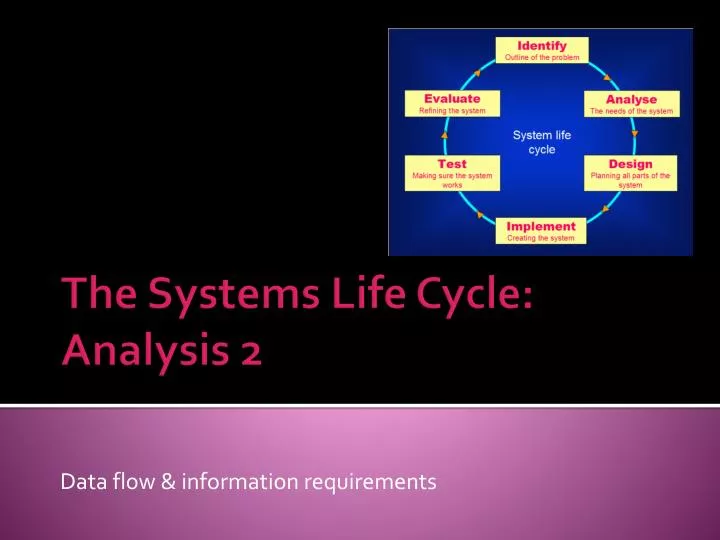
Data flow & information requirements The Systems Life Cycle: Analysis 2
Objectives: • Establishing IPSO • Recording information about the existing system • Identifying the problems with the system • Identifying User & Information requirements of the new system • Identifying HW & SW for a new system.
So far…. • Our analyst has collected information about the current system using questionnaires, observation, interviews and examining documents. • What happens next?
Step 2: • Need to identify all the inputs, processing & outputs in the existing system. • How?
1: Examination of documents This allows the analyst to establish which documents relate to information coming IN to the system, and which relate to information going OUT.
What happens to this information? • The analyst uses this knowledge to produce his own documentation of the system which helps him understand the system properly.
Each section… • ….needs to be examined to see the specific inputs, processes & outputs. • What would be the inputs of a payroll system? • The processes? • The outputs?
2 : Recording information about the current system • All results of fact-finding must be recorded • Accurate records are vital – why? • Because the system will evolve • Other analysts & programmers will need to develop the system even further at some point in the future.
How do we record the flow of data? • Data flow diagrams • These are a graphical method of recording the inputs, processing & outputs that have been identified.
Flow charts vs DFDs • Flow charts show the control flow of the program • DFDs show how the data flows around the entire system
3 : DFDS…. • Data flow diagrams illustrate how data is processed by a system in terms of inputs and outputs. • Have four components: • Terminators • Processes • Flow arrows • Stores
An example Orders Orders Customers Process order Order Information Rejected Orders Invoice data Invoices
An explanation Customers A Terminator - someone or something outside the system (eg a customer or a supplier) Data stores – where stored on paper or on a computer Invoices Data flow. It is important that the direction of the flow is accurately recorded. Process order Process order
Different levels of DFDs 0 • Level 0 • Very generalised • Shows terminators linked to current system eg Customers Customers Order Processing system
Different levels of DFDs 1 • Level 1: • Many more processes • More detail • Process boxes for both receiving orders and for producing invoices
Different levels of DFDs 2 • Level 2: • These show all aprts of the level 1 diagram in much more detail
DFDs: • Represent the way that data flows around the existing (old) system
System flowcharts • May be used, but generally are found in the design stage. • Represent the new system – the one that is going to be designed & implemented.
4 : Identifying problems with the current system • DFDs help the analyst to identify problems or weaknesses within the current system: • Eg data duplication • Job duplication • Unnecessary steps • Why is it necessary to identify these problems?
5 : Identifying suitable hardware & software for the new system • DFDs help the analyst decide on: • Appropriate methods of input • Approximate processor speed & memory • Size & number of storage devices • Quantity & format of output
6: Identifying the user & information requirements • The new system MUST meet the needs of the people who will use it • So – the analyst needs to know exactly what job each person does and what their requirements are. • He can the produce a Requirements Specification – a list of features of the system that are required.
Analysis Summary • Step 1 : collecting information on how the current system works • Step 2 : Establishing inputs, processes & outputs • Step 3 : recording information • Step 4 : Identifying problems • Step 5 : Identifying suitable hardware & software • Step 6 : Identifying user & information requirements