Download
1 / 121
1.29k likes | 1.75k Views
Computed Tomography in the Diagnostic Radiography Curriculum. My Disclaimer. My position on CT in the Diagnostic Curriculum is that it is more beneficial than harmful. I am not suggesting that students graduate from our Programs as CT techs.

E N D
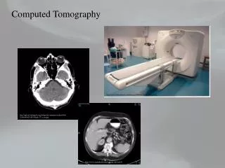
Computed Tomography in the Diagnostic Radiography Curriculum
My Disclaimer • My position on CT in the Diagnostic Curriculum is that it is more beneficial than harmful. • I am not suggesting that students graduate from our Programs as CT techs. • I AM suggesting that they have an understanding of the modality, its basic concepts, and focused clinical opportunities.
The Premise • I look at CT within the curriculum as a two-fold activity from the student perspective. • One, provides students a basic overview of what CT is, how it works, and why its ‘better’ for some diagnoses. • Two, CT provides an excellent means of review for general radiography principles that may be old hat for some, boring for others, or just offers a different perspective than the original explanations.
When to Present CT • CT has to be in the second year or later. There needs to be a foundation of relevance and understanding. • In our Program, CT is officially taught in the Rad T 265 course, first semester second year. • Clinical rotations begin in the middle of the first semester second year. • Unofficially CT is found throughout our second year curriculum.
Radiologic Technology 265 • Principles of Digital Imaging and Computer Applications(2)Prerequisite: Radiologic Technology 165. Introduction to computer aided medical imaging's as used in radiography departments. Applications include computed and digital radiography (CR/DR), CT, MRI, and other modalities. Basic imaging principles are applied, including physics, imaging protocols, and systems electronics. Software and display strategies for varying modalities will be discussed.
Date Lecture Topic Reading Assignment • Aug 28 Orientation/Principles of CT B. Ch 29, M v3 Ch 33 • Sep 4 HOLIDAY • Sep 11 Components of a CT scanner • Sep 18 Data Acquisition technology B. Ch 30 • Sep 25 Spiral CT • Oct 2 Image reconstruction • Oct 9 Image quality • Oct 16 Image manipulation M. Ch 36 • Oct 23 MRI physics and equipment • Oct 30 MRI image acquisition M. v. 3 Ch 36 • Nov 6 Computer literacy and its relevance B. Ch 26 • Nov 13 Basic concepts of digital imaging B. Ch 27, M v3 Ch 34 • Nov 20 Digital fluoroscopy M v 3 Ch 35, B. Ch 28 • Nov 27 Digital fluoroscopy • Dec 4 Ultrasound and Nuc. Med. Applications M v3 Ch 37&38 • Dec 11 FINAL
Why the importance of teaching CT? • Provides a break from the regular routine. • Offers ‘new’ technology or info that may be exciting. • Reviews existing (hopefully) knowledge. • For example, Photon/tissue interactions • Great way to review anatomy and pathology as seen clinically. • Provides an excellent opportunity to experience a modality first hand.
The Clinical Component • We began a clinical affiliation this year with a free-standing imaging center. • Last year, we had an observational agreement that allowed students to visit and only watch. • This year students have clinical expectations based on the time they spend there.
Clinical continued • Students are allowed to pick a three week optional rotation. • We chose this in order to have students doing something that interested them thereby decreasing the possibility of discontent. • Also, students looking for additional education, therapy or nuclear medicine, could get their observational requirements met.
The Proposed CT Curriculum • CT Generations • Components, Operations, and Processes • Radiation Protection Practices
CT Generations • This is really the only area that has limited value in the diagnostic curriculum.
First and Second Generation CT • The first and second generations of CT were very similar. • Both used a scanning technique called translate/rotate in order to move around the patient. • The first generation scanner used a single detector and thin beam. While the second generation scanner use several detectors and a fan beam. • These changes resulted in a significantly faster scanner.
Third Generation • The big change here was that the tube was in constant motion throughout the exposure, no more stops and starts. • The detectors were also moving during the exposure and more detectors were added. • As before, we now have an even faster scanner.
Fourth Generation • It became obvious that moving detectors introduces noise into the image. • Now the detectors are fixed in a ring around the patient and only the tube moves. • Thousands of detectors are now needed to generate an image. • Faster imaging with increased spatial resolution.
Fifth Generation • Electron beam CT • EBCT • Ultrafast
Spiral • Slip-ring technology eliminates power cables. • Constant power to moving tube. • Continuous exposure • Patient moves through the beam during exposure • A stream a data is generated (spiral) as opposed to a series of individual slices.
CT scanner generations have limited value outside of understanding CT. However, it does provide a mechanism to see the development of a modality. • Additionally, the advantages of each generation and its evolution illustrates the thought processes that go into learning and adapting.
Components, Operations, and Processes • Most of these topics have direct correlation to diagnostic radiography. • Data acquisition • Factors controlling image appearance • Anatomical structures • Post-processing
Data Acquisition • Methods • Slice by slice • Contiguous • Volumetric • Spiral/helical
Beam Geometry • Parallel • Fan • The traditional beam geometry, it is opened along the width of the patient. • Spiral • The beam is continuously on allowing for more anatomical coverage in a shorter time.
Data Acquisition system (DAS)Components • Tube • Detectors • Filters • Collimators • ADC
CT Tubes • Much higher heat loading than conventional tubes • 8MHU and up • Generally have two focal spots
Filters • Again CT filtration is similar to diagnostic radiography • All tubes are required to have minimum filtration • Primary purpose is patient protection • Also, in CT the filter is used to harden the beam; thereby, decreasing absoption • Compensating filters • ‘Bow-tie’ • Uniform beam intensity at the detectors • Think ‘wedge ‘ filter in diagnostic radiography.
CT Collimators • CT consists of both pre and post-patient collimation • Pre-patient collimation is analogous to the collimation we already know. • Controls beam coverage or amount of anatomy exposed.
Post-patient Collimation • Controls slice thickness. • Additionally, it serves to define the slice profile which provides a sort of grid effect. • Scatter rejection
Analog-to-Digital Convertor (ADC) • Converts the analog signal from the detectors to a digital signal for processing. • Rated by bits • Most scanners today are 16-bit systems • Produce 4096 data points • The more data points, the better the gray scale (contrast) resolution.
Measurement of the Transmitted Beam • A ray • Basically, the detected value of a single photon • Several rays combine to form a view. • The data from multiple photons hitting the detector during a single translation. • Profile • The electrical signal produced by the detector.
Encoding into Binary Data • The data from the views is converted into attenuation coefficients using the formula: • The attenuation coefficients are then sent to the ADC. 1 ___ lnIo/I = x
Data Transmission to the Computer • Data processing begins • The raw (detector) data is preprocessed to remove bad data sectors. • The reformatted raw data is now sent to the array processors. • The array processors are using filter algorithms to produce the desire image appearance, i.e. soft tissue, bone, high-res.
After the array processors, the data is then subjected to a reconstruction algorithm that produces the cross-sectional image we see. • The most common reconstruction algorithm today is the filtered back projection. • The data is now image data and available for image manipulation.
The CT Image • Any digital image, including CT, is comprised of picture elements (pixels). • The pixels are 2-dimensional elements that represent volume elements (voxels). • Pixels are displayed in a matrix. • The brightness of each pixel is determined by the CT number it represents.
CT Numbers • CT numbers are calculated by comparing the attenuation coefficients of water and tissue. • The formula is: CT # __ . __________ t w K = w
The CT number of water is ‘0’. • Now, if you look at the formula you can see that tissues attenuate more than water will have a positive CT number. • Conversely, tissues less attenuate less have negative CT numbers.
Examples of Tissue Attenuation Coefficients and Their CT Numbers
Factors Affecting Attenuation • Photon energy • Selected kVp • Filtration • Tissue effective atomic number • Tissue mass density
Selectable Scan Factors • Field of View • Scan • Display • Matrix size • Slice thickness • Algorithm • Scan time and rotational arc
Tube output • mAs • Region of Interest (ROI) • Magnification • FSS and Tube geometry
Scan FoV • The total area from which raw data is acquired
Display FoV • Determines how much raw data is used in displaying the acquired image.
Matrix Size • Basically, the number of pixels displayed. • Affects spatial resolution • The bigger the matrix the more pixels. • Given that image size stays the same the pixels have to be smaller; therefore, spatial resolution increases. • Generally, the larger the image matrix the higher the patient dose.
Algorithm • Mathematical formula applied to the raw data in order to produce a specific image outcome.
Radiographic Tube Output • mAs
ROI • Allows the technologist to select a specific area of interest for image reconstruction. • Uses the raw data for the reconstruction instead of using image data • The result is a better quality image.
Magnification • Defined as a post-processing activity. • Magnification uses image data not raw data, so the final product has less spatial resolution than when using ROI.
FSS and Tube Geometry • FSS • In CT, FSS selection has the same connotations it has in diagnostic radiography. • A smaller FSS has more detail (resolution) than a larger one. However, due to digital imaging issues (monitor and matrices) the effects of a small versus large FSS are not as apparent.
Factors Affecting Image Quality • Spatial resolution • Contrast resolution • Noise • Radiation dose • Artifacts
Spatial Resolution • The degree of blurring within the image • Ability to discriminate objects of varying density a small distance apart. • CT spatial resolution is affected by • Geometric factors • Reconstruction algorithm
Geometric Factors • FSS • Detector aperture width • Slice thickness • SID • SOD – distance to isocenter • Sampling distance • Number of projections
Reconstruction algorithms • Several different types of convolution algorithms are available. • Edge enhancement • Smoothing • Soft tissue • Bone • Matrix size is also going to play a role in spatial resolution