Download
1 / 19
220 likes | 460 Views
Chapter 8 EGR 260 – Circuit Analysis. 1. Reading Assignment: Chapter 8 in Electric Circuits, 9 th Ed. by Nilsson . 2 nd -order circuits have 2 independent energy storage elements (inductors and/or capacitors)

E N D
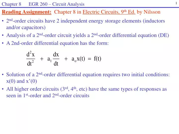
Chapter 8 EGR 260 – Circuit Analysis 1 Reading Assignment:Chapter 8 in Electric Circuits, 9th Ed. by Nilsson • 2nd-order circuits have 2 independent energy storage elements (inductors and/or capacitors) • Analysis of a 2nd-order circuit yields a 2nd-order differential equation (DE) • A 2nd-order differential equation has the form: • Solution of a 2nd-order differential equation requires two initial conditions: x(0) and x’(0) • All higher order circuits (3rd, 4th, etc) have the same types of responses as seen in 1st-order and 2nd-order circuits
Chapter 8 EGR 260 – Circuit Analysis 2 • Series RLC and Parallel RLC Circuits • Since 2nd-order circuits have two energy-storage types, the circuits can have the following forms: • 1) Two capacitors • 2) Two inductors • 3) One capacitor and one inductor • A) Series RLC circuit * • B) Parallel RLC circuit * • C) Others • * The textbook focuses on these two types of 2nd-order circuits Series RLC circuit Parallel RLC circuit
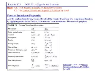
Chapter 8 EGR 260 – Circuit Analysis 3 Form of the solution to differential equations As seen with 1st-order circuits in Chapter 7, the general solution to a differential equation has two parts: where xh or xn is due to the initial conditions in the circuit and xp or xf is due to the forcing functions (independent voltage and current sources for t > 0). The forced response The forced response is due to the independent sources in the circuit for t > 0. Since the natural response will die out once the circuit reaches steady-state, the forced response can be found by analyzing the circuit at t = . In particular, x(t) = xh + xp = homogeneous solution + particular solution or x(t) = xn + xf = natural solution + forced solution xf = x()
Chapter 8 EGR 260 – Circuit Analysis 4 The natural response A 2nd-order differential equation has the form: where x(t) is a voltage v(t) or a current i(t). To find the natural response, set the forcing function f(t) (the right-hand side of the DE) to zero. Substituting the general form of the solution Aest yields the characteristic equation: s2 + a1s + ao = 0 Finding the roots of this quadratic (called the characteristic roots or natural frequencies) yields:
Chapter 8 EGR 260 – Circuit Analysis 5 • Characteristic Roots • The roots of the characteristic equation may be real and distinct, repeated, or complex. Thus, the natural response to a 2nd-order circuit has 3 possible forms: • 1) Overdamped response • Roots are real and distinct [ (a1)2 > 4ao ] • Solution has the form: • Sketch the form of the solution. • Discuss the concept of the dominant root.
Chapter 8 EGR 260 – Circuit Analysis 6 • 2) Critically damped response • Roots are repeated [ (a1)2 = 4ao ] so s1 = s2 = s = -a1/2 • Solution has the form: • Sketch the form of the solution.
Chapter 8 EGR 260 – Circuit Analysis 7 3) Underdamped response Roots are complex [ (a1)2 < 4ao ] so s1 , s2 = j Show that the solution has the form: Sketch the form of the solution. Discuss the concept of the exponential envelope. Sketch xn if A1 = 0, A2 = 10, =-1, and = . Sketch xn if A1 = 0, A2 = 10, =-10, and = 100.
Chapter 8 EGR 260 – Circuit Analysis 8 Illustration: The transient response to a 2nd-order circuit must follow one of the forms indicated above (overdamped, critically damped, or underdamped). Consider the circuit shown below. v(t) is 0V for t < 0 and the steady-state value of v(t) is 10V. How does it get from 0 to 10V? Discuss the possible responses for v(t) Define the terms damping, rise time, ringing, and % overshoot
Chapter 8 EGR 260 – Circuit Analysis 9 • Examples: When is each of the 3 types of responses desired? Discuss the following cases: • An elevator • A cruise-control circuit • The output of a logic gate • The start up voltage waveform for a DC power supply
Chapter 8 EGR 260 – Circuit Analysis 10 • Series and Parallel RLC Circuits • Two common second-order circuits are now considered: • series RLC circuits • parallel RLC circuits. • Relationships for these circuits can be easily developed such that the characteristic equation can be determined directly from component values without writing a differential equation for each example. • A general 2nd-order differential equation has the form: • A general 2nd-order characteristic equation has the form: • where • = damping coefficient • wo = resonant frequency s2 + 2s + wo2 = 0
Chapter 8 EGR 260 – Circuit Analysis 11 Series RLC Circuit - develop expressions for and wo
Chapter 8 EGR 260 – Circuit Analysis 12 Parallel RLC Circuit - develop expressions for and wo
Chapter 8 EGR 260 – Circuit Analysis 13 • Procedure for analyzing 2nd-order circuits (series RLC and parallel RLC) • 1. Find the characteristic equation and the natural response • Is the circuit a series RLC or parallel RLC? (for t > 0 with independent sources killed) • Find and wo2 and use these values in the characteristic equation: s2 + 2s + wo2. • Find the roots of the characteristic equation (characteristic roots or natural frequencies). • Determine the form of the natural response based on the type of characteristic roots: • Overdamped: Real, distinct roots (s1 and s2): • Underdamped: Complex roots (s1,s2 = j): • Critically damped: Repeated roots (s=s1=s2): • Find the forced response - Analyze the circuit at t = to find xf = x(). • Find the initial conditions, x(0) and x’(0). • A) Find x(0) by analyzing the circuit at t = 0- (find all capacitor voltages and inductor currents) • Analyze the circuit at t = 0+ (using vC(0) and iL (0) from step 3B) and find: • 4. Find the complete response • Find the total response, x(t) = xn + xf . • Use the two initial conditions to solve for the two unknowns in the total response.
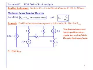
Chapter 8 EGR 260 – Circuit Analysis 14 Example: Determine v(t) in the circuit shown below for t > 0 if : A) R = 7 B) R = 2 C) R =
Chapter 8 EGR 260 – Circuit Analysis 15 Example: B) Continued with R = 2
Chapter 8 EGR 260 – Circuit Analysis 16 Example: C) Continued with R =
Chapter 8 EGR 260 – Circuit Analysis 17 Example:Determine v(t) in the circuit shown below for t > 0.
Chapter 8 EGR 260 – Circuit Analysis 18 Example:Determine v(t) in the circuit shown below for t > 0. Note: In determining if a circuit is a series RLC or parallel RLC circuit, consider the circuit for t > 0 with all independent sources killed.
Chapter 8 EGR 260 – Circuit Analysis 19 Example:Determine i(t) in the circuit shown below for t > 0. 20H