Download
1 / 40
560 likes | 1.37k Views
Geometric Dimensioning and Tolerancing. Unit 1 – Introduction, Symbols, and Terms. Geometric Tolerancing Workbook. Everyone should have a workbook to follow along. It contains necessary reference information along with class exercises.

E N D
Geometric Dimensioning and Tolerancing Unit 1 – Introduction, Symbols, and Terms
Geometric Tolerancing Workbook Everyone should have a workbook to follow along. It contains necessary reference information along with class exercises. Page numbers in yellow on the slides match pages in the workbook.
History and Background Eli Whitney, is the inventor of the cotton gin and a pioneer in the use of mass production methods. Around 1798, he won a contract to supply muskets to the United States government. The firearms manufacture were based on the concept of interchangeable parts. He made a presentation to congress by building 10 guns and assembling and disassembling them claiming the same exact parts and mechanisms. Eli Whitney 1765 - 1825
Tolerances • All dimensions require a tolerance. • A tolerance should be as large as possible without interfering with the function of the part to minimize production costs. • Consider how your part will be checked to see if it meets the tolerances.
Limit Tolerancing • Is the .620-.630 hole horizontal position measured from a true vertical plane or from the as built face? • A .005” tolerance on the horizontal and vertical position of the hole means that the position could be off by as much as.007”. max allowed error for hole center .007 +.005 perfect location for hole center +.005
Limit Tolerancing • Limit tolerances don’t have an origin or any orientation or location relative to datums. • The datums are usually implied. • The drawings are subject to different interpretations. • Plus/minus tolerancing works well for individual features of size (ex. diameter of a shaft), but does not control the relationship between individual features very well.
History of Dimensioning and Tolerancing Standards in the USA Mil Std 8 1950’s Mil Std 8A Mil Std 8B Mil Std 8C-1963 ASA-Y14.5-1957 USASI Y14.5-1966 ANSI Y14.5-1973 ANSI Y14.5M-1982 ASME Y14.5M-1994 ASME Y14.5-2009 1.3
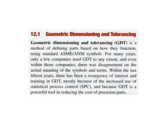
Introduction • GDT is a language of symbols • We will see an overview of the symbols associated with: • Dimensioning Symbols • Geometric Characteristics • Modifying Symbols
Dimensioning Symbols Diameter Radius R
Dimensioning Symbols Spherical Diameter S Spherical Radius SR
Dimensioning Symbols Controlled Radius Tolerance CR Number of Places A controlled radius has no ‘reversals’, but is a smooth curve within the tolerance zone.
Dimensioning Symbols Counterbore/Spotface Countersink
Dimensioning Symbols Depth/Deep Dimensions Not to Scale
Dimensioning Symbols Conical taper Slope
Dimensioning Symbols Square Reference Dimension
Dimensioning Symbols Dimension Origin Arc Length
Dimensioning Symbols All Around All Over
Dimensioning Symbols Chain Line Used to identify a limited region to be treated differently from the rest of the part.
Introduction • We will see an overview of the symbols associated with: • Dimensioning Symbols • Geometric Characteristics • Modifying Symbols
Geometric Characteristics Explained in detail in Chapters 6 and 8.
Introduction • We will see an overview of the symbols associated with: • Dimensioning Symbols • Geometric Characteristics • Modifying Symbols
Modifying Symbols Maximum Material Condition MMC MMC Refers to the size of the feature associated with the most material.
Modifying Symbols Least Material Condition LMC LMC Refers to the size of the feature associated with the least material.
Modifying Symbols Continuous Feature Basic Dimension Used to describe a theoretically exact size.
Modifying Symbols Between
Geometric Dimensioning and Tolerancing (GDT) • establish a reference coordinate system by defining datums • provide basic dimensions (perfect dimensions) relative to the datums • specify allowable tolerances
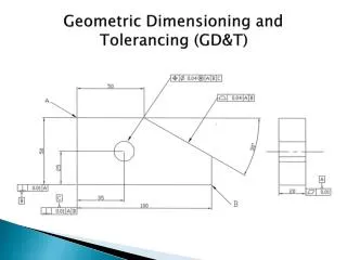
Common Symbols applied to a Drawing units are mm 25 10 18 ±1° 1.8
Indexer Assembly 1.17
Indexer Plate 1.17
Workshop Exercise 1.1 12 1.23