Download
1 / 13
150 likes | 405 Views
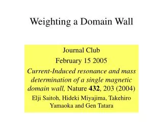
Learn about the magnetization process and domain wall motion in ferromagnetic materials under external magnetic fields, including reversible and irreversible processes. Explore hysteresis loops, domain configurations, and effects of impurities on domain wall motion.

E N D
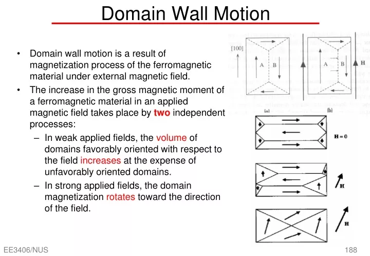
Domain wall motion is a result of magnetization process of the ferromagnetic material under external magnetic field. The increase in the gross magnetic moment of a ferromagnetic material in an applied magnetic field takes place by two independent processes: In weak applied fields, the volume of domains favorably oriented with respect to the field increases at the expense of unfavorably oriented domains. In strong applied fields, the domain magnetization rotates toward the direction of the field. Domain Wall Motion
A wall may be viewed as moving within one of a number of potential energy wells. With small fields, domains may move reversibly since they sit in small potential wells. This reversible region near the origin on the hysteresis loop. When applied field causes a local energy peak on an energy vs boundary position curve to be overcome, an irreversible boundary displacement occurs due to crystal imperfections and impurities which is not smooth. Domain walls and crystal imperfections interact: Wall becomes ‘pinned’ by defect or impurity and hence needs a greater applied field to break it free; once it snaps off, domain wall is moved until it is attracted by another imperfection where it is held until field increases further to snap it away again. Hence the motion of domain wall is rather jerky. Each time the domain wall snaps loose, lattice vibrations are generated. Domain wall motion is nonreversible and involves energy losses as heatto crystal. Effects of impurities on domain wall motion Energy picture Hysteresis loop
O-a region: reversible boundary motion Domain walls within various grains begin to move small distances Favorably oriented domains grow a little larger at expense of those pointing away from field. There is a small but net magnetization along field. a-b region: irreversible boundary motion Domain motions extend larger distances and walls meet obstacles such as crystal imperfections, impurities etc which tend to attract the walls and hinder their motions. Domain wall that is pinned by an imperfection cannot move until field increases sufficiently to provide necessary force to snap wall free jerky Sudden changes in magnetization involve energy conversion to heat and are irreversible. Domain Configuration Changes vs M-H Loop • At point c, crystal grain left with a single domain and magnetization in one of the easy direction. Net magnetization further increases. • c-d region: rotation of M • The magnetization will begin to rotate with respect to the applied magnetic field. • At point d, applied magnetic field increases to a value strong enough to align M along H, there are no domain walls and sample is said to be saturatedor the sample reaches saturation magnetizationMsat.
d-e region: rotation of M If field is decreased and removed, magnetization in each grain would rotate to align parallel with nearest easy direction in that grain. At point e, additional small domains may develop that reduce the magnetization within the grain. This leaves a permanent magnetization in sample, called remanent or residual magnetization. e-f region: demagnetization If now apply magnetizing field in reverse direction, magnetization of sample (still along +x) would decrease and eventually go to zero at sufficiently large field and sample is then totally demagnetized, as shown in point f. Magnetizing field Hc required to totally demagnetize sample is called the coercivityor coercive field. Domain Configuration Changes vs M-H Loop • This represents the resistance of the sample to demagnetization. Note that f has many domains new domains created during demagnetization. • f-g region: similar to a-d • If field continues to increase in –x direction, process from point f onwards to point g would be similar from a to d.
Coercivity Residual magnetization (Mr) Coercivity or coercive field (Hc) If we monitor B instead of M, then we have a B-H loop If subject a sample to cyclic applied field alternating between +x and –x direction, then hysteresis loop would be different than that when sample is taken to saturation. Magnetic field does not reach Bsatbut instead some Bmwhen field is Hm. There is a hysteresis effect because magnetization and demagnetization processes do NOT retrace each other. Area enclosed within loop is energy dissipated per unit volume per cycle of applied field oscillation.
Demagnetizing If we try demagnetizing the sample with remanent magnetization at point e by applying reverse field, then magnetization would move along point e to f. If applied field is suddenly switch off at f, B does not remain zero but recovers along f to some point e’ and attains Br’. Reason: small domain wall motions are reversible as soon as field is removed. Can anticipate this by removing field at some point f’. sample recovers along f’O to zero magnetization. But this requires knowing the exact B-H behaviour and exact location of f’.
Deperming Hence easiest way to demagnetize sample is to cycle H with ample magnitude to reach saturation and then to continue cycling H with gradually decreasing magnitude. Sample traces out smaller and smaller loops until loops are so small that they end up at origin when H reaches zero. This demagnetization process is known as deperming. All the discussion indicates that it is not possible to ‘back-track’ domain configurations and each state or domain configuration of the magnet depends very much on its history.
Magnetic Materials • Pre-requisites • Magnetization and Susceptibility • Type of Magnetism • Ferromagnetic Domains • Soft and Hard Materials
Ferromagnetic materials are divided into two broad classes: softmagnetic materials and hardmaterials: Soft magnetic materials: easy to magnetize and demagnetize; require relatively low magnetic field intensities; narrow B-H loops; show high initial permeability and low coercive force; power loss per cycle is small since hysteresis loop has small area. An ideal soft magnet has zero coercivity (Hc), very large saturation magnetization (Bsat), zero remanent magnetization (Br), zero hysteresis loss, and very large maximum and initial permeability Suitable for applications where repeated cycles of magnetization and demagnetization are involved, e.g.: electric motors, transformer, inductors or magnetic head. Soft and Hard Materials
Hard magnetic materials: hard to magnetize and demagnetize; require high magnetic field intensities; broad and almost rectangular B-H loops; show low initial permeability and high coercive force. They may be used for disk media or permanent magnet application. An ideal hard magnet has very large coercivity and remanent field. The energy stored per unit volume in the external magnetic field should be as large as possible since this is energy available to do work. This energy depends on max value of BH product (denoted (BH)max) in the second quadrant of the B-H loop.