Download
1 / 13
130 likes | 252 Views
Arrangement of Carbon Nanotube Using by Electrokinetics. 學生 : 鄭宜肪 Q28961054 劉晉維 Q26964098. 授課老師 : 李旺龍 副教授. Impedance. Time. Saturation state. Without binding. During Binding. ISFET Nanosenaor Utilized CNT Bridging. Motivation. How to align the carbon nanotubes direction?.

E N D
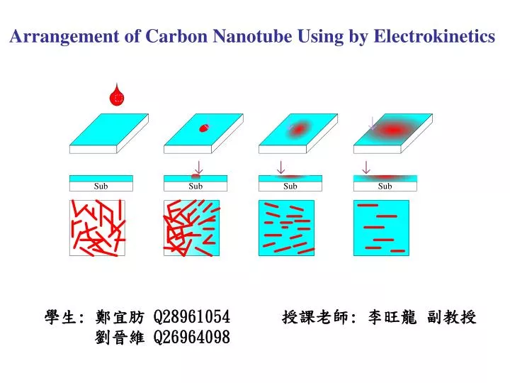
Arrangement of Carbon Nanotube Using by Electrokinetics 學生: 鄭宜肪 Q28961054 劉晉維 Q26964098 授課老師: 李旺龍 副教授
Impedance Time Saturation state Without binding During Binding ISFET Nanosenaor Utilized CNT Bridging
Motivation How to align the carbon nanotubes direction? How to bridge the carbon nanotubes between source and drain electrodes? Utilized surface tension force source drain Utilized electrical force CNT
- U + _ _ _ _ _ _ _ +++++++++++++++++++++++++ _ _ _ _ _ _ _ _ _ _ _ _ _ __ _ _ _ + 導體基板 Theory of Electrowetting
V AC voltage q 0 Chip Treatment Cleaning substrate 4~5 mm AZ 4620 Spin coating dielectric layer ITO glass Tefelon AZ 4620 Spin coating hydrophobic layer ITO glass
Contact Angle Change During Voltage Applied Before applied voltage! Appling voltage! A little change! Electric condition: 200 Vp-p, 1 kHz
Contact Angle Change During Voltage Applied Before applied voltage! Appling voltage! Large change! Electric condition: 400 Vp-p, 1 kHz
High Voltage Break Effect Bubble generation! Dielectric layer broken!
-q +q Dielectrophoretic (DEP) Technology • Conventional dielectrophoresis, as first defined by Pohl, is the motion imparted on electrically polarised particles subjected to non-uniform electric fields. Dipole moment -We defined the product of the charge q and the vector d (going from – q to + q) as the electric dipole moment + -
_ _ _ _ _ A + m + + + + + + + _ m B _ _ DEP Force by Non-uniform Field FDEP = 2 m r3 Re[ fCM (ω)] E2 r: particle radius fCM (ω) = (εp* – εm* / εp* + 2εm*) : Clausius - Mossitti factor ε * = ε - jσ /ω, σ: conductivity,ε:permittivity ω= 2πf, f : frequency Re[K()]> 0 : positive DEP Re[K()]< 0 : negative DEP + |εp *| > | εm*| |εp*| < | εm* | Medium - Plate electrode
AC voltage electrode electrode + - Utilized electric field! The Concept of CNT Alignment Using by Eletrokinetic Force CNT Induced dipole moment E Nano wire would be induced dipole moment through electric polarization ! Dipole moment will arrange align with the electric field!
Dielectrophoretic Trapping and Bridging 以鏈球桿菌進行模擬! Buffer condition: 10 mM KCl (σ=1.4 mS/cm) Electric condition: 14 VPP, 5 MHz
Conclusion • The dielectric layer using by AZ 4620 PR that the Break • down voltage is 500 VPP, the promising applied voltage • range of change contact angle is from 200 VPP to 400 VPP. • 2.Dielectrophoresis method to align the wire or rod • shapes object is very possible to bridge them between • the two electrodes. • 3. We would be manipulated CNT combine with • electrowetting and Dielectrophoresis to enhance • CNT bridging efficiency.