Download
1 / 85
880 likes | 979 Views
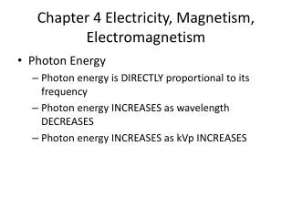
Learn about magnetic field, coils, flux density, magnetomotive force, magnetic circuits, and Faraday's law in this comprehensive guide to magnetism and electromagnetism in engineering.

E N D
Magnetism and Electromagnetism Engr. Faheemullah Shaikh
Wire Coil • Notice that a current carrying coil of wire will produce a perpendicular field
Magnetic Field: Coil • A series of coils produces a field similar to a bar magnet – but weaker!
Magnetic Field Flux Ф can be increased by increasing the current I, Ф I I
Magnetic Field Flux Ф can be increased by increasing the number of turns N, Ф N N I
Magnetic Field Flux Ф can be increased by increasing the cross-section area of coil A, Ф A N A I
Magnetic Field Flux Ф can be increased by increasing the cross-section area of coil A, Ф A N I A
Magnetic Field Flux Ф is decreased by increasing the length of coil l, 1 Ф l l N I A
μ0 NIA Ф = l Magnetic Field Therefore we can write an equation for flux Ф as, NIA Ф l l N or I A
μ0 NIA Ф = l Magnetic Field Where μ0is vacuum or non-magnetic material permeability μ0 = 4π x 10-7 H/m
Solenoid If a coil is wound on a steel rod and connected to a battery, the steel becomes magnetized and behaves like a permanent magnet.
Magnetic Field: Coil • Placing a ferrous material inside the coil increases the magnetic field • Acts to concentrate the field also notice field lines are parallel inside ferrous element • ‘flux density’ has increased
μNIA Ф = l Magnetic Field By placing a magnetic material inside the coil, l N Where μ is the permeability of the magnetic material (core). I A
μNIA Ф = l Magnetic Field By placing a magnetic material inside the coil, l N Where μ is the permeability of the magnetic material (core). I A
Permeability • Permeability μ is a measure of the ease by which a magnetic flux can pass through a material (Wb/Am) • Permeability of free space μo = 4π x 10-7 (Wb/Am) • Relative permeability:
Reluctance • Reluctance: “resistance” to flow of magnetic flux Associated with “magnetic circuit” – flux equivalent to current • What’s equivalent of voltage?
Magnetomotive Force, F • Coil generates magnetic field in ferrous torroid • Driving force F needed to overcome torroid reluctance • Magnetic equivalent of ohms law
Magnetomotive Force • The MMF is generated by the coil • Strength related to number of turns and current, measured in Ampere turns (At)
Magnetic Field Intensity • The longer the magnetic path the greater the MMF required to drive the flux • Magnetomotive force per unit length is known as the “magnetizing force” H • Magnetizing force and flux density related by:
l l μ A μ Electric circuit: Emf = V = I x R Magnetic circuit: mmf = F = Φ x = H x l = (B x A) x = (B x A) x = B x = H x l
Magnetic Force On A Current – Carrying Conductor • The magnetic force (F) the conductor experiences is equal to the product of its length (L) within the field, the current I in the conductor, the external magnetic field B and the sine of the angle between the conductor and the magnetic field. In short F= BIL (sin)
The force on a current-carrying conductor in a magnetic field: • When a current-carrying conductor is placed in a magnetic field, there is an interaction between the magnetic field produced by the current and the permanent field, which leads to a force being experienced by the conductor:
The magnitude of the force on the conductor depends on the magnitude of the current which it carries. The force is a maximum when the current flows perpendicular to the field (as shown in diagram A on the left below), and it is zero when it flows parallel to the field (as in diagram B, on the right):
Fleming's left hand rule (for electric motors) Fleming's left hand rule shows the direction of the thrust on a conductor carrying a current in a magnetic field. The left hand is held with the thumb, index finger and middle finger mutually at right angles. The First finger represents the direction of the Field. The Second finger represents the direction of the Current (in the classical direction, from positive to negative). The Thumb represents the direction of the Thrust or resultant Motion.
The directional relationship of I in the conductor, the external magnetic field and the force the conductor experiences I B F
Faraday’s Law Magnetic Field can produce an electric current in a closed loop, if the magnetic flux linking the surface area of the loop changes with time. This mechanism is called “Electromagnetic Induction” The electric Current Produced Induced Current
Faraday’s Law First Experiments Move a bar magnet toward the loop, a current suddenly appears in the circuit Conducting loop The current disappears when the bar magnet stops Sensitive current meter If we then move the bar magnet away, a current again suddenly appears, but now in the opposite direction Since there is no battery or other source of emf included, there is no current in the circuit
Faraday’s Law Discovering of the First Experiments • A current appears only if there is relative motion between the loop and the magnet 2. Faster motion produces a greater current 3. If moving the magnet’s N-pole towards the loop causes clockwise current, then moving the N-pole away causes counterclockwise.
Faraday’s Law Current in the coil produces a magnetic field B An Experiment - Situation A Constant flux though the loop DC current I, in coil produces a constant magnetic field, in turn produces a constant flux though the loop Constant flux, no current is induced in the loop. No current detected by Galvanometer
Faraday’s Law Deflection of Galvanometer needle An Experiment - Situation B: Disconnect battery suddenly Magnetic field drops to zero Sudden change of magnetic flux to zero causes a momentarily deflection of Galvanometer needle.
Faraday’s Law Sudden change of magnetic flux through the loop Current in the coil produces a magnetic field B An Experiment - Situation C: Reconnect Battery Magnetic field becomes non-zero Deflection of Galvanometer needle in the opposite direction Link: http://micro.magnet.fsu.edu/electromag/java/faraday/index.html
Faraday’s Law Conclusions from the experiment • Current induced in the closed loop when magnetic flux changes, and direction of current depends on whether flux is increasing or decreasing • If the loop is turned or moved closer or away from the coil, the physical movement changes the magnetic flux linking its surface, produces a current in the loop, even though B has not changed In Technical Terms Time-varying magnetic field produces an electromotive force (emf) which establish a current in the closed circuit
Faraday’s Law Electromotive force (emf) can be obtained through the following ways: 3. A combination of the two above, both flux changing and conductor moving simultaneously. A closed path may consists of a conductor, a capacitor or an imaginary line in space, etc. 1. A time-varying flux linking a stationary closed path. (i.e. Transformer) 2. Relative motion between a steady flux and a close path. (i.e. D.C. Generator)
Faraday’s Law Faraday summarized this electromagnetic phenomenon into two laws ,which are called the Faraday’s law • Faraday’s First Law • When the flux magnet linked to a circuit changes, an electromotive force (emf) will be induced.
Faraday’s Second Law The magnetic of emf induced is equal to the time rate of change of the linked magnetic flux F. Faraday’s Law (volts) Minus Sign Lenz’s Law Indicates that the emf induced is in such a direction as to produces a current whose flux, if added to the original flux, would reduce the magnitude of the emf
Faraday’s Law Minus Sign Lenz’s Law The induced voltage acts to produce an opposing flux
Faraday’s Law Minus Sign Lenz’s Law The induced voltage acts to produce an opposing flux
Faraday’s Law Minus Sign Lenz’s Law The induced voltage acts to produce an opposing flux
Heinrich F.E. Lenz • Russian physicist • (1804-1865) • 1834 Lenz’s Law • There is an induced current in a closed conducting loop if and only if the magnetic flux through the loop is changing. • Indicates that the emf induced is in such a direction as to produces a current whose flux, if added to the original flux, would reduce the magnitude of the emf
There is an induced current in a closed conducting loop if and only if the magnetic flux through the loop is changing. The direction of the induced current is such that the induced magnetic field always opposes the change in the flux.
Right Hand Rule • If you wrap your fingers around the coil in the direction of the current, your thumb points north.
2 Direction of induced current b Lenz's law In both cases, magnet moves against a force. Work is done during the motion & it is transferred as electrical energy. Induced Ialways flows to oppose the movement which started it.
S N rails “eddy” current Applications of Magnetic Induction • Magnetic Levitation (Maglev) Trains • Induced surface (“eddy”) currents produce field in opposite direction Repels magnet Levitates train • Maglev trains today can travel up to 310 mph Twice the speed of Amtrak’s fastest conventional train!
Liner induction 0-70 mph in 3 sec