Download
1 / 40
430 likes | 524 Views
Explore computational models for wind energy systems and rotorcraft aerodynamics using hybrid CFD techniques. Discuss challenges, experiments, and future directions in renewable energy research.

E N D
Computational Modeling of Wind Turbine Aerodynamics and Helicopter Hover Flow Using Hybrid CFD Dr. Sven Schmitz University of California, Davis Pennsylvania State University April 21st, 2010
Outline • Wind Energy • The NREL Phase VI Experiment • Hybrid CFD for Wind Turbines • Hybrid CFD for Helicopter Hover Flow • Future Research Directions
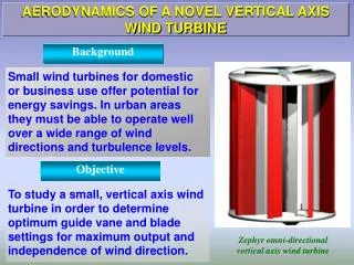
“Alternative Sunrise” Windkraftanlage Holzweiler mit Braunkohlekraftwerk Grevenbroich, Germany, April 2010. Wind Energy • Free energy source • Emission free • No water use • Scalability, i.e. ‘local’ & ‘wind power plant’ • Less dependence on fossil fuels
Wind Energy - U.S. Market • Over 10,000 MW installed in 2009 - U.S. world leader • Top U.S. Wind Turbine Supplier : GE Energy • Wind industry supports 85,000 jobs in 50 states • Now 9 wind turbine manufacturers in U.S. www.awea.org/reports (April 2010)
Wind Energy - Incentives • US DOE – Energy Efficiency and Renewable Energy • 20% Wind Energy by 2030 • Pennsylvania - Alternative Energy Investment Act (2009) • Wind Energy Supply Chain Initiative (WESCI)
Wind Energy - Power Curve • r and W site specific • CP≈ 0.52 at Wrated (CP,Betz = 0.59) • Rotor Diameter D driving factor
O & M estimated at 10%-20% of total COE. • Availability & Loss are site & design specific. Aerodynamics & Aeroelasticity Wind Energy - Cost of Energy (COE) [Walford, C., SAND2006-1100]
Wind Energy - Cost Reduction • Maximize Availability, Minimize Loss • Improved designs for Region II • Reduce fatigue loads • Minimize Operation and Maintenance (O & M) • Reduce # turbines to maintain by increasing turbine power • Reduce fatigue loads
Wind EnergyChallenges in Computational Modeling • Unsteady Aerodynamics • Blade load response to wind gust • Aeroelasticity • Blade tip deflections of several meters • Twist changes > 10deg • Airfoil Soiling • Performance loss caused by dirt, insects, etc.
The NREL Phase VI Experiment NREL = National Renewable Energy Laboratory • NREL Phase VI Rotor, April 2000 • R = 5.03m • 2 Blades, Twist, Taper • Stall-controlled, S809 Airfoil [Somers, NREL/SR-440-6918] • 5m/s < VWind < 25m/s • W = 72rpm • P ≈ 10KW NREL Phase VI Rotor in NASA Ames 120’ x 80’ wind tunnel
The NREL Phase VI Experiment • Blind Comparison Run, December 2000 Comparison of computational models • Performance Codes (BEMs) • Aeroelastic Codes • Wake Codes • CFD Codes NREL Phase VI Rotor in NASA Ames 120’ x 80’ wind tunnel
The NREL Phase VI Experiment Main Results from Blind Comparison Run [NREL/TP-500-29494] • No-Yaw, Steady-State, No-Stall conditions … Turbine Power Prediction : 25% - 175% of measured Blade Bending Prediction : 85% - 150% of measured CFD Codes -> Overall best predictions of turbine power and blade loads. Wake Codes -> Good performance for attached flow. Conclusions from Blind Comparison Run [NREL/TP-500-29494]
Hybrid CFD for Wind Turbines Difficulties of computational models • CFD Codes : High Computational Cost & Artificial Dissipation • Wake Codes : Prediction of strong 3D effects close to the rotor blade Reduce cost and dissipation. Near-Field RANS + Far-Field Wake Code = Hybrid CFD for Wind Turbines
Hybrid CFD for Wind Turbines Navier-Stokes Biot-Savart Law (discrete) Boundary of Navier-Stokes Zone Vortex Method Bound Vortex Converged for … Vortex Filament Parallelized Coupled Solver (PCS)
Hybrid CFD for Wind Turbines Average uBfrom power estimate using actuator disc theory Biot-Savart Law Vortex Method
Hybrid CFD for Wind Turbines Accuracy of straight-line Vortex Segmentation : => [Gupta & Leishman, AIAA-2004-0828] ΔΘ = 10˚ => Error < 10% ΔΘ < 2.5˚ => Error < 1% C Vortex Method • Parameters for accurate • calculation of induced velocities : • Minimum Number of Vortex Filaments : 39 • Trefftz Plane Location : 20 blade radii behind the rotor disc • Vortex Segmentation ΔΘ : 0.02˚ at the blade, 12˚ after 1 revolution Accuracy achieved in Induced Velocities at representative points : < 1%
Hybrid CFD for Wind Turbines PCS = Parallelized Coupled Solver VLM = Vortex Line Method [J.J. Chattot] Inviscid Flow : VLM PCS Thrust [N] 509.62 508.31 Tangential Force [N] -183.63 -179.89 Bending Moment [Nm] 1803.1 1814.8 Torque [Nm] -588.82 -583.80 Power [kW] 8.879 8.804 Difference in Power : 0.84 % Optimum Wind Turbine [S. Schmitz, J. J. Chattot, Computers & Fluids (2006)]
Hybrid CFD for Wind Turbines VLM PCS Thrust [N] 472.41 458.60 PCS = Parallelized Coupled Solver VLM = Vortex Line Method [J.J. Chattot] Tangential Force [N] -163.26 -150.80 Viscous Flow : Bending Moment [Nm] 1670.2 1636.4 Torque [Nm] -519.58 -485.50 Power [kW] 7.835 7.321 Difference in Power : 6.6 % Optimum Wind Turbine [S. Schmitz, J. J. Chattot, Computers & Fluids (2006)]
Hybrid CFD for Wind Turbines NREL Phase VI Rotor Rotating, S-Sequence Fully Attached Flow : U=7m/s
Hybrid CFD for Wind Turbines NREL Phase VI Rotor Very good agreement w/ measured surface pressure coefficient. [S. Schmitz, J. J. Chattot, ASME JSEE (2005)]
Hybrid CFD for Wind Turbines NREL Phase VI Rotor Influence of Vortex Sheet Revolutions on Rotor Torque : VWind = 7m/s Collaboration with GE Wind Wind Aero Design Tool Development (2007-2009) UCD Award #08003057, #700163655 Routine Design Use
Hybrid CFD for Wind Turbines NREL Phase VI Rotor • Other CFD Results • [Duque et al, AIAA-1999-0037] • [Sezer-Uzol, Long, AIAA-2006-0394] • [Potsdam, Mavriplis, AIAA-2009-1221]
Hybrid CFD for Wind Turbines NREL Phase VI Rotor Application of PCS to the NREL Phase VI Rotor : Steady (no yaw), Fully Turbulent, k-ε and k-ω turbulence models • VLM = Vortex Line Model • [J. J. Chattot , CFD Journal (2002)] • PCS = Parallelized Coupled Solver • [S. Schmitz, J. J. Chattot, ASME JSEE (2005)]
Hybrid CFD for Wind Turbines Distribution of Bound Circulation (Parked, L – Sequence, U = 20.1 m/s) Good agreement between VLM and PCS for attached flow. Apparent Differences for separated flow (3D effects) A ‘Trailing Vortex’ is attached to a region of stalled flow. [Schreck, AIAA-2005-0776] [Tangler, AIAA-2005-0591] Attached Flow Separated Flow Stalled Flow Trailing Vortex @ r/R=0.40 NREL Phase VI Rotor [S. Schmitz, J. J. Chattot, ASME JSEE (2006)]
Hybrid CFD for Wind Turbines Visualization of ‘Trailing Vortex’ by an Iso-Vorticity Surface (a) a47 = 3.53deg (b) a47 = 13.46deg (c) a47 = 23.49deg (d) a47 = 33.50deg Iso-Vorticity Surface behind Parked NREL PhaseVI Blade (w=19s-1) (L – Sequence, U = 20.1 m/s) NREL Phase VI Rotor [S. Schmitz, J. J. Chattot, ASME JSEE (2006)]
Hybrid CFD for Helicopter Hover Flow complex physics need for high accuracy a recurring engineering need many methods developed, few validated little data that supports complete physical models Collaboration with US Army AFDD A New CFD Approach for the Computation of General Rotorcraft Flows (2006-2010) UCD Award #NNX08AU38A, #NNA0CB79A
Hybrid CFD for Helicopter Hover Flow Typical HELIX-IA-hybrid grid topology Coupling UMTURNS w/ HELIX-IA • HELIX-IA provides wake structure and induced inflow. • Interpolate HELIX-IA velocity to UMTURNS boundary. • Impose Blade Circulation from UMTURNS to HELIX-IA Wake. 91x125x107 193x65x96
Hybrid CFD for Helicopter Hover Flow HELIX-IA : An Iterative Eulerian- / Lagrangian Solution Process Vorticity Embedding
Hybrid CFD for Helicopter Hover Flow Vorticity Embedding Roll Up – Vortex Sheet w/ Elliptical Loading (Qv Field) t = p [S. Schmitz et al, AIAA-2009-3856]
Hybrid CFD for Helicopter Hover Flow Vorticity Embedding Roll Up – Pair of Vortex Ring Sheets t = 0.0 t = p/4 t = 2p [S. Schmitz et al, AIAA-2009-3856]
Hybrid CFD for Helicopter Hover Flow Validation : Model UH-60A Blade
Hybrid CFD for Helicopter Hover Flow Radial Axial Axial/Radial Tip Vortex Trajectory ComparisonsModel UH-60A Rotor – CT/s = 0.085, Mtip=0.63 [S. Schmitz et al, AHS Journal (2009)]
Hybrid CFD for Helicopter Hover Flow r/R = 0.92 r/R = 0.865 r/R = 0.945 r/R = 0.965 Pressure Coefficient vs. x/c Model UH-60A Rotor – CT/s = 0.085, Mtip=0.63 [S. Schmitz et al, AHS Journal (2009)]
Hybrid CFD for Helicopter Hover Flow Pressure Coefficient vs. z/c Model UH-60A Rotor – CT/s = 0.085, Mtip=0.63 [S. Schmitz et al, AHS Journal (2009)]
Hybrid CFD for Helicopter Hover Flow Figure-of-Merit vs. CTModel UH-60A Rotor – CT/s = 0.085, Mtip=0.63 [S. Schmitz et al, AHS Journal (2009)]
Hybrid CFD for Helicopter Hover Flow Typical HELIX-IA-hybrid grid topology Coupling UMTURNS w/ HELIX-IA • Fast and robust • Accurate wake computation • Suggests that hover data are insufficient
Future Research Directions Combining experiences & resources in Wind Energy and Rotorcraft HYBRID U-RANS/POTENTIAL SOLVER • Outer Wake Solver • Vorticity-Embedding Potential Solver, HELIX-IA • For steady flow comparable to Biot-Savart • Possibility for efficient free wake computation • Inner U-RANS Solver • OverFlow, CFX, UMTURNS, etc.
Future Research Directions y=0deg U-RANS Solve N blades Vortex Model Converged or # subiterations Converged BC – u,v,w y=y+Dy # Revolutions until solution is periodic. Understanding the Unsteady Aerodynamics is vital for future competitiveness of Wind Energy. HYBRID U-RANS/POTENTIAL SOLVER
Future Research Directions Acoustics (Brentner, McLaughlin, Morris) Aeroelasticity (PSU VLRCOE) HYBRID U-RANS/POTENTIAL SOLVER Airfoil Soiling (Brasseur, Maughmer) Mesoscale Modeling (Brasseur, Haupt) Current Funding : GE Wind, US Army AFDD Future Funding : DOE, NSF, NREL, State of Pennsylvania, GE Wind, US Army AFDD
Wake Interactions at ‘Horns Rev’, Denmark Hybrid CFD for Wind TurbinesFuture fast & accurate wind turbine/plant designs