Download
1 / 35
360 likes | 395 Views
This document outlines the requirements, architecture, and technologies for the data acquisition and trigger systems at CERN's Large Hadron Collider (LHC). It covers event builder design, detector channels, event rates, storage capacities, and trigger rates for p-p collisions at the LHC. The structure of the ATLAS, CMS, ALICE, and LHCb experiments' data acquisition systems is detailed, along with trends and advancements in DAQ technologies. It discusses the evolution from minicomputers to modern network-based systems, emphasizing the need for high-speed data processing and transportation to handle the massive amounts of data produced by the LHC experiments.

E N D
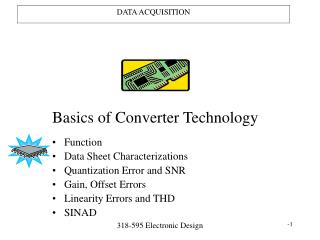
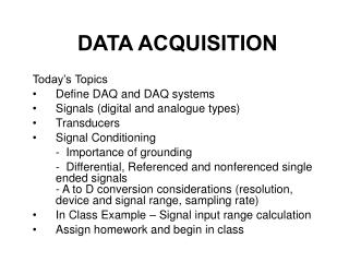
CMS Data Acquisition S. Cittolin CERN/PH-CMD Oct. 7 2004 LHC DAYS IN SPLIT Requirements and Architecture Trigger and Readout Event Builder and Technologies Plans and summary
p-p collisions at LHC Operating conditions: Higgs in 4 muons + ~20 minimum bias All charged tracks with pt > 2 GeV Event rate Level-1 Event Rates: ~109 Hz Event size: ~1 MByte On tape Level-1 Output 100 kHz Mass storage 102 Hz Event Selection: ~1/1013 Reconstructed tracks with pt > 25 GeV
Requirements and design parameters Detectors Detector Channels Control Ev. Data Pixel 60000000 1 GB 50 (kB) Tracker 10000000 1 GB 650 Preshower 145000 10 MB 50 ECAL 85000 10 MB 100 HCAL 14000 100 kB 50 Muon DT 200000 10 MB 10 Muon RPC 200000 10 MB 5 Muon CSC 400000 10 MB 90 Trigger 1 GB 16 Event size 1 Mbyte Max LV1 Trigger 100 kHz Online rejection 99.999% System dead time ~ %
LHC trigger and DAQ summary ATLAS No.Levels First Level Event Readout Archive Trigger Rate (Hz) Size (Byte) Bandw.(GB/s) MB/s (Event/s) 3 105 106 10 100 (102) LV-2 103 2 105 106 100 100(102) 3 LV-0 106 2x10⁵ 4 40 (2x10²) LV-1 4 104 4 Pp-Pp5005x107 51250 (102) p-p 103 2x10⁶ 200 (102) CMS LHCb ALICE
CMS DAQ structure: 2 physical triggers Level-1 Trigger Custom design 40 MHz Clock driven Custom processors High-Level Trigger Industry products 100 kHz Event driven PC network Level-1 output / HLT input 100 kHz Network bandwidth 1 Terabit/s HLT output 102 Hz Invest in data transportation and CPU
Evolution of DAQ technologies and structures 1970-80: Minicomputers Readout custom design First standard: CAMAC • kByte/s 1980-90: Microprocessors HEP standards (Fastbus) Embedded CPU, Industry standards (VME) • MByte/s 2000-xx: Networks IT commodities, PC, Clusters Internet, Web, etc. • GByte/s
DAQ baseline structure Collision rate 40 MHz Level-1 Maximum trigger rate 100 kHz Average event size ≈ 1 Mbyte Event Flow Control ≈ 106 Mssg/s No. of In-Out units 512 Readout network bandwidth ≈ 1 Terabit/s Event filter computing power ≈ 106 SI95 Data production ≈ Tbyte/day No. of PC motherboards ≈ Thousands
Two trigger levels • Level-1: Specialized processors • 40 MHz synchronous • Particle identification: • high pT electron, muon, jets, missing ET • - Local pattern recognition and energy evaluation on prompt macro-granular information from calorimeter and muon detectors 99.99 % rejected 0.01 Accepted High trigger levels: CPU farms 100 kHz asynchronous farms - Clean particle signature - Finer granularity precise measurement - Kinematics. effective mass cuts and event topology - Track reconstruction and detector matching - Event reconstruction and analysis 100-1000 Hz. Mass storage Reconstruction and analysis. 99.9 % rejected 0.1 Accepted
IO and Processing systems : Commercial PCs IO and Processing systems : Commercial PCs Operating systems : Unix(Linux) Operating systems : Unix(Linux), Interfaces standards : PC IO systems (e.g. PCI) Interfaces standards : PC IO systems (e.g. PCI) Readout and computing IO structures 200X: PCI-X … • 2002 PC mother boards: • - 2 GHz dual processors • 4 PCI-X ports at 1GB/s • 3 GB/s memory bandwidth • Suitable for all DAQ readout applications
Building the event (EVB) Event builder : Physical system interconnecting data sources with data destinations. It has to move each event data fragments into a same destination Event fragments : Event data fragments are stored in separated physical memory systems 2 1 3 1 2 3 512 512 Full events : Full event data are stored into one physical memory system associated to a processing unit 512 Data sources for 1 Mbyte events ~1000s HTL processing nodes
EVB and switch technologies • MyricomMyrinet 2000 • Switch:Clos-128 x 2.5 Gb/s port • NIC: M3S-PCI64B-2 (LANai9) • Custom Firmware Implementation : 16x16 port X-bar capable of channeling data between any two ports. wormhole data transport with flow control at all stages • Gigabit Ethernet • • Switch: FoundryFastIron 64 x 1.2Gb/s port • • NIC: Alteon (running standard firmware) Implementation: Multi-port memory system of R/W access bandwidth greater than the sum of all port speeds Packet switching Contention resolved by Output buffer. Packets can be lost. Infiniband • 2.5 Gb/s demo product. Tests ongoing with a small 2x2 setup
link (2 Gbps) EVB 1x1 EVB 8x8 EVB 32x32 link (2 Gbps) BS@NIC EVB - fixed size 32x32 Myrinet EVB protocols results Random traffic 250 200 8x8: single stage: max. utilization: 50% 150 100 32x32: two stage network max. utilization 30% 50 Throughput per Node (MB/s) 0 10 100 1000 10000 100000 Fragment Size (Byte) Working point Barrel shifter 250 200 • Fixed size event fragments • below 4k: Fragment < BS carrier • above 4k: Fragment > BS carrier • Throughput at 234 MB/s • = 94% of link Bandwidth 150 100 50 0 10 100 1000 10000 100000
1x1 32x32 link BW (1Gbps) link BW (1Gbps) TCP/IP p2p 32x32 TCP/IP EVB 32x32 32x32 GbE EVB protocols results Raw packets (L2 frames) 140 120 1x1 • Point to point asymptotically to 125 MB/s • 32x32 saw tooth due to MTU • above 10k: plateau of 115 MB/s • ie 92% of link speed (1Gbps) 100 32x32 80 60 40 20 Throughput per Node (MB/s) 100 1000 10000 100000 Fragment Size (Byte) 140 TCP/IP 120 100 • Point to pointAt 800 B: 88 MB/s (70%). • No improvement if host CPU733 -> 1000 MHz • [with Jumbo frames 110 MB/s (88%)] • 32x32at 16 kB75 MB/s (60% load) 80 60 40 20 100 1000 10000 100000
EVB demonstrators summary Myrinet 2000 GbE raw packet GbE TCP/IP Test bench 32x32 32x32 32x32 Port speed 2.5 Gbit/s 1.2 Gbit/s 1.2 Gbit/s Random traffic 30-50% 50%, 92%(*) 30%, 60%(*) Barrel switch94% - - CPU load Low High High 1 Tbit/s EVB 512x512 1024x1024 2048x2048 No. switches 8 128-Clos 16 256-port 32 256-port Industry standards Proprietary standards (*) with fragment sizes larger than 16kB
USC Data to surface SCX Readout Builders 2 stages: Data to surface & Readout Builder 2 kByte 16 kByte FED Builder (64 units) 8x8 x 5 Gb/s switch Event fragments merger Readout Builder (up to 8) 64x64 x 2.5 Gb/s switch Event rate 12.5 kHz
16k USC Data to surface 2k 4k Readout Builders SCX Builders protocols (e.g. Myrinet) Random traffic 8x8(x2) switches 50% load Barrel shifter 64x64 switch 90% load
USC Data to surface Readout Builders SCX DAQ staging : 1 to 8 RBs = 100 kHz 12.5 kHz +12.5 kHz +12.5 kHz
USC Data to surface Readout Builders SCX I) Data to surface (D2S) Data to surface: Average event size 1 Mbyte No. FED S-link64 ports 700 DAQ links (2.5 Gb/s) 512+512 Event fragment size 2 kB FED builders (8x8 dual) 64 Technology(2004) Myrinet Data link and FED builders technologies are independent from the Readout Builder ones. Myrinet is the default solution. Decision must be taken in 2004. Installation in 2005
USC Data to surface Readout Builders SCX II) Readout Builders (RB) Readout Builders (x8): Lv-1 max. trigger rate 12.5 kHz RU Builder (64x64) .125 Tbit/s Event fragment size 16 kB RU/BU systems 64 Event filter power 105 SI95 EVB technology (2006) Open Readout builders technologies are independent from the D2S one. Decision will be taken later in 2006
Data to surface: Average event size 1 Mbyte No. FED S-link64 ports 700 DAQ links (2.5 Gb/s) 512+512 Event fragment size 2 kB FED builders (8x8 dual) 64 Technology(2004) Myrinet Readout Builders (x8): Lv-1 max. trigger rate 12.5 kHz RU Builder (64x64) .125 Tbit/s Event fragment size 16 kB RU/BU systems 64 Event filter power 105 SI95 EVB technology (2006) Open 8-fold DAQ 3-D design
On-line software : framework and subsystems Online software architecture : • Cross-platform DAQ framework: XDAQ • Data acquisition components • Run Control and Monitor System (RCMS) • Detector Control System (DCS) The RCMS, DCS and data acquisition components interoperate through a distributed processing environment called XDAQ (cross-platform DAQ framework)
Configuration, operation and monitoring RCMS: Run Control and Monitoring System Based on open protocols, web services and emerging e-tools tools (JAVA, http, XML, MySQL, ….) • XDAQ:on-line framework and DAQ components: • Services and tools for local and remote inter-process communication, configuration and control and data storage Components to build data acquisition systems (RU,BU,EVM,..) • (C++, JAVA, I2O, http, XML, SOAP) DCS: Detector Control Systems Based on industry supported hardware and software (PLC, field buses, PVSS and JCOP tools)
DAQ raw schedule D2S production Preseries Installation Readout integration & UCX Commissioning On-line software DAQ integration & SCX Commissioning
2004 P5 green barrack: Pre-series RB • 32 GII-FED emulators • 64 FRLs • 13 Water cooled racks • 93 PC dual-CPU • D2S Myrinet equipment • Readout Builder Myrinet • 16 PC Filter Farm
Preseries integration programme 32 GIII FED emulators Up to 32 detector FED 64 FRLs 8 8x8 FED builders 4 FRL crates 64x64 RU builders 16 FUs Filter SF 200m fibers Data links + XDAQ, DAQ applications, Run Control, DCS/DSS, Mass storage, DBs
10 TeraIPS 10 TeraIPS CMS data flow and on(off) line computing To regional centers To regional centers 622 Mbit/s 622 Mbit/s Remote Remote control rooms control rooms Controls: Controls: 1 Gbit/s 1 Gbit/s Events: Events: 5 TeraIPS 5 TeraIPS 10 Gbit/s 10 Gbit/s Controls: Controls: 1 Gbit/s 1 Gbit/s Raw Data: Raw Data: 1000 Gbit/s 1000 Gbit/s
DAQ data flow and computing model Event rate Level-1 HLT output
Summary design principles • Invest in the advance of communication and processing technologies • Computing (100 kHz Readout, HLT by PC farms) • Communication (Terabit/s networks, GB/s memories) • Maximally scaling architecture • Exploit technology evolution • Cost optimization viastaged installation • Modular system (simpler controls, error handling, smaller basic units) • Rely on hardware and software industry standards • Custom/standards (PCI, Ethernet, C++, JAVA, http, XML,..)
Conclusions The CMS design fulfils the major requirements: • 100 KHz level-1 readout • Event builder: a scalable structure that can go up to 1 Terabit/s • High-Level Trigger by fully programmable processors • This design should be considered complete, but not final. e.g. switches procured in 2008-09 can be different from those of the startup system • It is a system that is expected to changewith time, accelerator and experiment conditions. And it has been designed to do so • It is conceived to provide the maximum possible flexibility to execute a physics selection on-line