Download
1 / 16
180 likes | 414 Views
Lecture 23. ANNOUNCEMENTS Midterm #2 results (undergrad. scores only): N=73; mean=63 ; median=63.5 ; std.dev.=8.42 You may pick up your exam during any TA office hour. Regrade requests must be made before you leave with your exam.

E N D
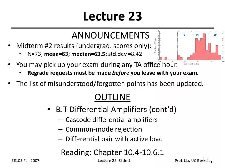
Lecture 23 ANNOUNCEMENTS • Midterm #2 results (undergrad. scores only): • N=73; mean=63; median=63.5; std.dev.=8.42 • You may pick up your exam during any TA office hour. • Regrade requests must be made before you leave with your exam. • The list of misunderstood/forgotten points has been updated. OUTLINE • BJT Differential Amplifiers (cont’d) • Cascode differential amplifiers • Common-mode rejection • Differential pair with active load Reading: Chapter 10.4-10.6.1 6 44 21
Cascode Differential Pair Half circuit for ac analysis
Telescopic Cascode Differential Pair Half circuit for ac analysis
Example Half circuit for ac analysis
Effect of Finite Tail Impedance • If the tail current source is not ideal, then when an input common-mode voltage is applied, the currents in Q1 and Q2 and hence the output common-mode voltage will change.
Effect of Input CM Noise Ideal Tail Current • There is no effect of the input CM noise at the output.
Effect of Input CM NoiseNon-Ideal Tail Current • The single-ended outputs are corrupted by the input CM noise.
Comparison • The differential output voltage signal is the same for both cases. For small input CM noise, the differential pair is not affected. Ideal Tail Current Non-Ideal Tail Current
CM to DM Conversion; gain ACM-DM • If finite tail impedance and asymmetry (e.g. in load resistance) are both present, then the differential output signal will contain a portion of the input common-mode signal.
Common-Mode Rejection Ratio • CMRR is the ratio of the wanted amplified differential input signal to the unwanted converted input common-mode noise that appears at the output.
Differential to Single-Ended Conversion • Many circuits require a differential to single-ended conversion. • This topology is not very good; its most critical drawback is supply noise corruption, since no common-mode cancellation mechanism exists. Also, we lose half of the voltage signal.
… A Better Alternative • This circuit topology performs differential to single-ended conversion with no loss of gain.
Active Load • With a current mirror as the load, the signal current produced by Q1 can be replicated onto Q4. • This type of load is different from the conventional “static load” and is called an “active load.”
Differential Pair with Active Load • The input differential pair decreases the current drawn from RL by I, and the active load pushes an extra I into RL by current mirror action; these effects enhance each other.
Active Load vs. Static Load • The load in the circuit on the left responds to the input signal and enhances the single-ended output, whereas the load in the circuit on the right does not.