Download
1 / 31
320 likes | 609 Views
Chapter 11 - Part 2 Data Link Control. 11-6 HDLC. High-level Data Link Control (HDLC) is a bit-oriented protocol for communication over point-to-point and multipoint links. It implements the ARQ mechanisms we discussed in this chapter. Topics discussed in this section:.

E N D
Chapter 11 - Part 2 Data Link Control
11-6 HDLC High-level Data Link Control (HDLC) is a bit-oriented protocol for communication over point-to-point and multipoint links. It implements the ARQ mechanisms we discussed in this chapter. Topics discussed in this section: Configurations and Transfer ModesFramesControl Field
What is HDLC? • HDLC is one of the oldest example of Data link protocol • Still elements of that protocol are used in other more recent protocols • The protocol defines the following points: • transfer modes and configurations • Frames structure and rates • Meanings of the different fields in the frame • Following examples explain the operation of the protocol, how the communication between two ADJACENT NODES is realized (who sends what and when…)
Configurations and transfer modes HDLC provides two transfer modes: - normal response mode (NRM) – unbalanced configuration; primary and secondary station; used for point to-point and point-to-multipoint links; - asynchronous balanced mode (ABM) – balanced configuration; point-to-point link; most common mode today;
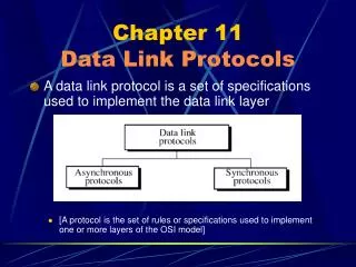
HDLC frames each type is used as an envelope for the transmission of a different message – information (data), supervisory (control), unnumbered (system management)
Control fields for different frame types Control field for I-frames: - flow and error control using piggybacking (N(S) and N(R) fields; max window size 8; P/F – poll (frame sent from a primary to a secondary station) or final (from secondary to primary); Control field in S-frames: - code fields: ready receive - RR + N(R) ACK number; receive not ready – RNR+N(R) (frame came but is being processed) REJ (NAK) + N(R) – rejects only last frame; SREJ + N(R) – rejects corrupted frame
Example 11.9 Figure 11.29 shows how U-frames can be used for connection establishment and connection release. Node A asks for a connection with a set asynchronous balanced mode (SABM) frame; node B gives a positive response with an unnumbered acknowledgment (UA) frame. After these two exchanges, data can be transferred between the two nodes (not shown in the figure). After data transfer, node A sends a DISC (disconnect) frame to release the connection; it is confirmed by node B responding with a UA (unnumbered acknowledgment).
Example 11.10 Figure 11.30 shows an exchange using piggybacking. Node A begins the exchange of information with an I-frame numbered 0 followed by another I-frame numbered 1. Node B piggybacks its acknowledgment of both frames onto an I-frame of its own. Node B’s first I-frame is also numbered 0 [N(S) field] and contains a 2 in its N(R) field, acknowledging the receipt of A’s frames 1 and 0 and indicating that it expects frame 2 to arrive next.
Example 11.10 – cont’d Node B transmits its second and third I-frames (numbered 1 and 2) before accepting further frames from node A. Its N(R) information, therefore, has not changed: B frames 1 and 2 indicate that node B is still expecting A’s frame 2 to arrive next. Node A has sent all its data. Therefore, it cannot piggyback an acknowledgment onto an I-frame and sends an S-frame instead. The RR code indicates that A is still ready to receive. The number 3 in the N(R) field tells B that frames 0, 1, and 2 have all been accepted and that A is now expecting frame number 3.
Example 11.11 Figure 11.31 shows an exchange in which a frame is lost. Node B sends three data frames (0, 1, and 2), but frame 1 is lost. When node A receives frame 2, it discards it and sends a REJ frame for frame 1. Note that the protocol being used is Go-Back-N with the special use of an REJ frame as a NAK frame. The NAK frame does two things here: It confirms the receipt of frame 0 and declares that frame 1 and any following frames must be resent. Node B, after receiving the REJ frame, resends frames 1 and 2. Node A acknowledges the receipt by sending an RR frame (ACK) with acknowledgment number 3.
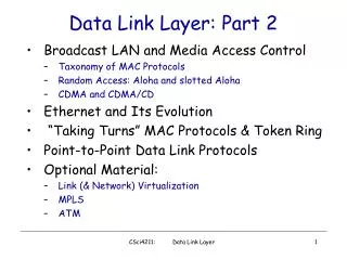
11-7 POINT-TO-POINT PROTOCOL Although HDLC is a general protocol that can be used for both point-to-point and multipoint configurations, one of the most common protocols for point-to-point access is the Point-to-Point Protocol (PPP). PPP is a byte-oriented protocol. Topics discussed in this section: Framing Transition Phases Multiplexing Multilink PPP
Point-to-point protocol (PPP) Most common protocol for point-to-point links (i.e. Internet users connecting to the service provider using a modem – physical line is the telephone line; data link layer is for control and managing of data transfer) Provided services: - defines the frame format to be exchanged between devices - defines how to establish the link and exchange of data - defines DLL encapsulation - defines authentication of communicating devices - provides services for a number of network layer protocols - provides connections over multiple links - provides network address configuration (home user needing a temporary network address to connect to the Internet)
Point-to-point protocol (PPP) – cont’d but .. it doesn’t provide the following: - flow control – a sender can send frames one after the other with no concern of overwhelming the receiver - very simple mechanism for error control – simple CRC; if a frame is corrupted it is discarded and the upper layer must take care of the problem - does not provide addressing mechanism for multipoint configuration
Point-to-point protocol (PPP) – frame format Flag:starts and ends with 01111101 (one byte) Address: constant value 11111111; can be omitted Control: constant value 11000000; can be omitted Protocol: defines what is carried in the data field (user data or other information Payload: user data or other information; max 1500 bytes; byte-stuffed; fixed size so needs padding FCS: 2 byte or 4 byte standard CRC.
Transmission Phases Dead: link is not used; no active carrier at the PHY layer and the link is quiet Establish: when one of the nodes starts the communication; options are negotiated; if successful, system goes into next phase Authenticate: optional phase; send special authentication packets Network:negotiation for the network layer protocols (because it supports multiple NL protocols) Open:data transfer takes place; until one of the endpoints wants to terminate the connection; Terminate: several packets are exchanged for noise cleaning and closing the link
Multiplexing in PPP Uses other protocols to establish the link; authenticate the parties involved; carry network data layer;
Multiplexing in PPP Link control protocol: responsible for establishing, maintaining, configuring and terminating links. Provides negotiation mechanisms for deciding on the options before the link is established. 0xC021 – defines LCP LCP packet: code – type of packet (see tb.11.2) ID – matches a request with a reply length information (variable)
Authentication validating the identity of the user who needs to access a set of resources Password Authentication Protocol (PAP): 1. The user who wants to access the system sends an authentication identification (user name and password) 2. The system checks the validity and either accepts or denies the connection.
Authentication – cont’d Challenge Handshake Authentication Protocol (CHAP): 1. System sends the user a challenge containing a challenge value (few bytes) 2. The user applies a predefined function that takes the challenge value and the user’s own password and creates a result. User sends the result in a response packet. 3. System does the same. If the result is the same as the one sent by the user access is granted; otherwise it is denied.
Network Control Protocols PPP supports different network layer protocols (Internet, OSI, Xerox, DECnet, AppleTalk, Novel etc.). To do this it needs a separate control protocol for each of these: IPCP configures the link for carrying IP data packets; Xerox CP – Xerox protocol data packets etc. Example: IPCP (Internet Protocol Control Protocol) most popular; uses seven types of packets distinguished by their code values (see table 11.4 next slide)
Multilink PPP PPP defined for point-to-point links; but the availability of multiple channels in a single link motivated the development of multipoint PPP. Logical PPP frame is divided into several actual PPP frames; To show that actual PPP is a fragment of a logical PPP protocol field is set to 0x003d. Adds complexity; requires sequence numbers;
Example 11.12 Let us go through the phases followed by a network layer packet as it is transmitted through a PPP connection. Figure 11.41 shows the steps. For simplicity, we assume unidirectional movement of data from the user site to the system site (such as sending an e-mail through an ISP). The first two frames show link establishment. We have chosen two options (not shown in the figure): using PAP for authentication and suppressing the address control fields. Frames 3 and 4 are for authentication. Frames 5 and 6 establish the network layer connection using IPCP.