Download
1 / 40
440 likes | 704 Views
Learn about electromagnetic induction, transformer design, power efficiency, voltage relationships, and different transformer applications.

E N D
Transformers Test Friday 3/30/12
Generator Electromagnetic Induction Induction is the process of producing (inducing) a voltage by passing a wire through a magnetic field.
In induction one of two things must be happening!! • The magnetic field is moving. • The wire is moving.
input output
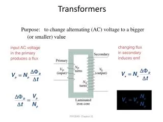
A transformer works with AC voltages, since the magnetic field must be changing to induce a voltage in the coils.
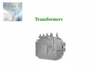
Transformer Designing a Transformer • Frequency • Voltage • Power
Transformer Rating Transformer are rated in Volt-Amperes (VA) Volt Amperes are used to determine the Maximum Current the transformer can handle.
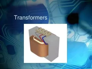
A transformer consists of two coils of wire wound around a core of soft iron.
The side connected to the input AC voltage source is called the primary and has NP turns. NP NS
The other side, called the secondary, is connected to a load and has NS turns. NS
Core The core is used to increase the magnetic flux and to provide a medium for the flux to pass from one coil to the other
Coefficient of Coupling • The measure of how good the transformer is. • Scale of 0 to 1 • 1 – All the magnetic Flux lines cut the Secondary Winding • 0 – None of the magnetic Flux lines cut the Secondary Winding
Mutual Inductance The fact that a change in the current of one coil affects the current and voltage in the second coil is quantified in the property called mutual inductance.
Turns Ratio The turns ratio of a transformer is the ratio of number of windings of primary side to the secondary side of the transformer. NP NS
Turns Ratio = NP NS NS NP
Voltage Relationships The voltages are related by: NP VP NS VS =
Voltage Relationships When NS > NP, the transformer is referred to as a step-up transformer. Voltage Increases
Voltage Relationships When NS < NP, the transformer is referred to as a step-downtransformer. Voltage Decreases
Power The power input into the primary equals, at best, the power output at the secondary. IPVP = ISVS Power In = Power Out
Power IPVP = ISVS • (This assumes an ideal transformer.) If VS increases, as in a step up transformer, IS must decrease. If VS decreases, as in a step down transformer, IS must increase.
Power Efficiency • You don’t get something for nothing!!!! • In real transformers, power efficiencies typically range from 90% to 99% (0.9 to 0.99)
VP=100v Vs=? Rs=1kΩ NP= 250 NS= 500
VPNS NP 100v X 500 250 VS = VS = VS = 200V
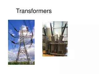
750,000 volts 7,200 volts 240 volts
Transformer Applications Impedance Matching (Ω) More Power is Transfered!!!
Transformer Applications Phase Shifting
Transformer Applications Isolation • Passes Signal unchanged • Prevents Electric Shock
Transformer Applications Blocking DC DC
Transformer Applications Produce Multiple VoltagesMulti-Tap Transformer
Transformer Applications Autotransformer • Step-Up or Step-Down • No Isolation!!!
VP=100v Rs=1kΩ NP= 250 NS= 500
Ch 12: AC • Pages 122 – 128 • Answer Question through Chapter • Write down Questions and Answers • AC Worksheets: 2-1 • Lab 1: Book 2 “DC and AC” • Problem Worksheets • 4 Simulations – Computer Lab Due 3/26th Test 3/26th
Ch 18: Transformers • Pages 168 – 174 • Answer Question through Chapter • Write down Questions and Answers • Transformer Worksheets: Lab 2-14 • Lab: 29 Old Book • Problem Worksheets • Video Worksheet – “Generating Electricity” Due 3/26th Test 3/26th