Download
1 / 38
410 likes | 738 Views
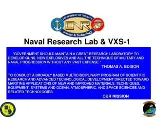
VXS Cover. VME Switched Serial. “VXS” is a trademark of VITA. VXS Overview. Adds switched serial interconnect(s) to the VME architecture coincident with the VMEbus parallel bus. Employs standard open technology for the serial switched links.

E N D
VXS Cover VME Switched Serial “VXS” is a trademark of VITA
VXS Overview • Adds switched serial interconnect(s) to the VME architecture coincident with the VMEbus parallel bus. • Employs standard open technology for the serial switched links. • Accommodates multiple switched serial technologies, but not necessarily at the same time. • Utilizes MULTIGIG RT 2 connector in P0 position. Demonstrated to support 10 Gb/s. • Pulls additional DC power onto each VME card over existing P1/P2 pins (VITA 1.7). • Maintains backward compatibility.
VXS Family of Standards ANSI/VITA Standard VXS 41.0 VMEbus Switched Serial Base Specification Draft Standard VXS 41.1 InfiniBand Protocol Layer VXS 41.3 GbE Protocol Layer VXS 41.5 Aurora Protocol Layer VXS 41.8 10GbE Protocol Layer VXS 41.2 Serial RapidIO Protocol Layer VXS 41.4 PCI Express Protocol Layer VXS 41.6 1x Gigabit Ethernet Control Channel Layer VXS 41.10 Live Insertion System Requirements
Relative Bus Performance Bus performance is a reason to use VME!
Why VXS? • The most demanding applications (e.g. SPE, radar, sonar, image processing, etc.) require: • High performance, scalable processing power • Very high data transfer capabilities • Extremely low latency • Currently these applications make use of: • VMEbus for “control plane” communication • A proprietary or quasi-standard bus for “data plane” communication • Standard interfaces are now able to address these needs and provide: • Less Contention • Increased Scalability • Less Routing Real Estate • Higher Bandwidth • Low Latency
Multiple Topologies Dual Star Single Star Mesh
VXS components Alignment and Protocol Keying Example backplane Note: not all backplanes would need a switch! Payload board Switch board P0 connector 200 insertions Courtesy Tyco Electronics www.multigigrt.com
P 1 SwItch slot Logical connections to switch card VMEbus Slot 1 P1 P1 Slot 5 An example 8 user-slot, 1 switch card backplane P0 P0 P0 P 2 P2 P2 Slot 2 P1 P1 Slot 6 VXS Switch Card (no VME) P0 P0 P2 P2 Slot 1 link Fabric Switch Slot 2 link Slot 3 P1 Slot 7 Slot 3 link P0 P0 Slot 4 link P2 Slot 5 link Slot 6 link Slot 4 P1 Slot 8 Slot 7 link P0 Slot 8 link P2 VXS Switch Card Connection Example
VME – VXS Compatibility All of these cards can coexist in the same VXS chassis Fabric Only VXS(no parallel bus) VXS + 2eSST VME 2eSSTVME Legacy VME Capability Switched Serial Compatible Parallel Bus Compatible VXS Backplane
Payload Board Top Handle P1 K0 P0 Front Panel 4 HP P2 Bottom Handle Photo courtesy of TEK Microsystems, Inc.
VXS: Connectors VITA 41 payload board P0 connector VITA 41 switch card P1-P5 connectors
VXS Products CSP Inc. M16 Switch TEK Microsystems, Inc. Atlas Pentek, Inc. 4207 TEK Microsystems, Inc. ADC-DCA
VXS Products Hartmann VXS Backplane Elma VXS 18 Slot
VXS Details
VXS is Fabric Agnostic • VXS provides multi Gb/sec serial switched fabric capability to EurocardVMEbus form factor using P0 • Accommodates multiple interconnect technologies • 41.1 – InfiniBand • 41.2 – Serial RapidIO • 41.3 – 1000BaseCX Ethernet • 41.4 – PCI Express • 41.5 – Aurora • 41.6 – 1x Gigabit Ethernet Control • 41.8 – 10GbEthernet
Performance for the Future! VXS Generation 3 (6.4 Gbps links) VXS Generation 2 (5.0 Gbps links) VXS Generation 1 (3.125 Gbps links) VME 2eSST w/Tsi148 VME64 MBLT w/Tsi148 VME64 MBLT 1 MB/s 10 MB/s 100 MB/s 1 GB/s 10 GB/s 100 GB/s VXS = 8 lanes/slot x 18 slots/chassis
VXS Market Opportunities • Program requirements are demanding VXS solutions! • VXS allows existing deployed systems to scale in compute capacity and capability while preserving past hardware and software investments. New applications with the same I/O. • Combat Vehicle Systems • Medical: CT, MRI, X-Ray • VXS permits customers to migrate to, and bridge from, current legacy interconnects to unifying high performance network. • Navy Shipboard Systems • VXS permits high speed data pipes and content alongside real time processing. • Airborne ISR
Example Fabric PinoutVITA 41.2 • RapidIO Pinout • Each payload board supports up to two 4X Serial RapidIO ports.
VXS is NOT limited to the configuration depicted in the example diagram of the 41.0 base spec! VXS Backplane Configuration - Maximum Dual star Single star Daisy chain Small mesh Photo courtesy of Elma Electronic, Inc.
VXS Alternate Backplane Configurations 6VXS + 2 switch Photo courtesy of Elma Electronic, Inc. 6 VXS + 1 switch + 1 VME64X Photo courtesy of Hartmann Electronic 18 VXS + 2 switch + 1 VME64X Photo courtesy of Hartmann Electronic
VXS No Switch Slot Configuration • No switch • Active backplane switching All of these configurations and topologies use the same VXS payload board 3 slot - 0 switch, 3 payload
RTM Keying Solution Rear Alignment Front Alignment M2 Screw IEC 61076-4-101 Keying
CASE: Clustering CPU Resources - Challenge • Customer Challenge - Consolidate computing, preserve existing I/O designs and interfaces, design an architecture that will scale computing capability. Computing and I/O is now distributed throughout the vehicle in various sub-assemblies
CASE: Clustering CPU Resources- Solution • VXS Solution - Consolidate computing into single chassis with low latency high speed interconnect (InfiniBand), bridge to existing VMEbus I/O designs with VMEbus repeater. SWITCHES Switched-serial backplane fabric provides ability to scale and cluster computing resources.
PLATFORM 1 • Post Processing • Not co-located with sensor • Large integrated data payload • PLATFORM 2 • Sensor front-end • Real-time requirements • Customer-specific VMEbus designs CASE: Data Pipes & Real Time Requirements • Customer Challenge – Integrate sensor front-end processing with post-processing. Reduce the time from information acquisition to action. Integrate high speed data pipes with real time sensor processing. NETWORK SENSOR SUITE
CASE: Data Pipes & Real Time Requirements • VXS Solution – High speed local interconnect and computing integrated with customer-specific front-end processing. One platform for real-time processing, high speed content processing, distribution. SWITCHES
CASE: Clustering CPU Resources • Customer Challenge - Consolidate computing, preserve existing I/O designs and interfaces, design an architecture that will scale computing capability. Computing and I/O is now distributed throughout the vehicle in various sub-assemblies
CASE: Clustering CPU Resources • VXS Solution - Consolidate computing into single chassis with low latency high speed interconnect (InfiniBand), bridge to existing VMEbus I/O designs with VMEbus repeater. SWITCHES Switched-serial backplane fabric provides ability to scale and cluster computing resources.
System Domain 2 System Domain 1 ) ) ) L L L LAN LAN LAN CASE: Evolve to Single Interconnect • Customer Challenge – Evolve to a single high performance network interconnect, maintain interfaces to existing network and data links on proven VME hardware, consolidate networking across system application domains. • Ethernet • 1553 • SCSI • FDDI • ATM • MIL-STD-1397 • MIL-STD-751 • HIPPI • RS-232/422 • Other System Domain 3
CASE: Evolve to Single Interconnect • VXS Solution – Provide a unifying high performance interconnect while supporting the wide range of existing legacy interconnects supported on qualified VMEbus board level product. Gateway to existing interfaces, enables integration and unification of the network, bandwidth in and out of the box, supports “spiral development”