Download
1 / 25
430 likes | 1.2k Views
Physics 121 - Electricity and Magnetism Lecture 12 - Inductance, RL Circuits Y&F Chapter 30, Sect 1 - 4. Inductors and Inductance Self-Inductance RL Circuits – Current Growth RL Circuits – Current Decay Energy Stored in a Magnetic Field Energy Density of a Magnetic Field Mutual Inductance

E N D
Physics 121 - Electricity and MagnetismLecture 12 - Inductance, RL Circuits Y&F Chapter 30, Sect 1 - 4 • Inductors and Inductance • Self-Inductance • RL Circuits – Current Growth • RL Circuits – Current Decay • Energy Stored in a Magnetic Field • Energy Density of a Magnetic Field • Mutual Inductance • Summary
Magnetic Flux: • Faraday’s Law: A changing magnetic flux through a coil of wire induces an EMF in the wire, proportional to the number of turns, N. • Lenz’s Law: The current driven by an induced EMF creates an induced magnetic field that opposes the flux change. Bind & iind oppose changes in FB • Induction and energy transfer: The forces on the loop oppose the motion of the loop, and the power required to sustain motion provides electrical power to the loop. i1 • Transformer principle: changing current i1 in primary induces EMF and current i2 in secondary coil. i2 • Generalized Faraday Law: A changing magnetic flux creates non-conservative electric field. Induction: basics
Example: Find the electric field induced by changing magnetic flux Assume: dB/dt = constant over circular region. Find the magnitude E of the induced electric field at points within and outside the magnetic field. Due to symmetry and Gauss’ Law, E is tangential: For r < R: So For r > R: So The magnitude of induced electric field grows linearly with r, then falls off as 1/r for r>R
Example: EMF generated Faraday Disk Dynamo Conducting disk, radius R, rotates at rate w in uniform constant field B, FLUX ARGUMENT: areal velocity w, q + USING MOTIONAL EMF FORMULA: Emf induced across conductor length ds (Equation 29.7) Moving conductor sees vXB as electric field E’ For points on rotating disk: v = wr, vXB = E’is radially outward, ds = dr current flows radially out dA = area swept out by radius vector in dq = fraction of full circle in dq x area of circle
N • Changing current in a single coil generates magnetic field and flux • Flux Change induces flux opposing the change, along with opposing EMF and current. • This back EMF limits the rate of current (and therefore flux) change in the circuit • For increasing current, back EMF limits the rate of increase • For decreasing current, back EMF sustains the current Inductance measures oppositon to the rate of change of current Self-Inductance: Analogous to inertia • ANY magnetic flux change is resisted • Changing current in a single coil induces a “back EMF” • Eind in the same coil opposing the current change, an • induced current iind, and a consistent induced field Bind. • TWO RELATED FARADAYS LAW EFFECTS: • Mutual-induction: di1/dt in “transformer primary” induces EMF and current i2 in “linked” secondary coil (transformer principle). • Self-induction in a single Coil: di/dt produces “back EMF” due to Lenz & Faraday Laws: Find opposes dF/dt due to current change. Eind opposes di/dt.
Joseph Henry 1797 – 1878 Why choose this definition? Cross-multiply……. Take time derivative • L contains all the geometry • EL is the “back EMF” Another form of Faraday’s Law! Definition of Self-inductance Recall capacitance: depends only on geometry It measures charge stored per volt Self-inductance depends only on coil geometry It measures flux created per ampere number of turns flux through one turn depends on current & all N turns self-inductance cancels current dependence in flux above SI unit of inductance:
where Field: + Flux in just one turn: ALL N turns contribute to self-flux through ONE turn L - Apply definition of self-inductance: RL • N turns • Area A • Length l • Volume V =Al • Depends on geometry • only, like capacitance. • Proportional to N2 ! Check: Same L if you start with Faraday’s Law for FB: Note: Inductance per unit length has same dimensions as m0 forsolenoid use above Example: Find the Self-Inductance of a solenoid
l Ideal inductor (abstraction): Non-ideal inductors have internal resistance: · = - = E V ir measured voltage L IND · Direction of ir depends on current r L · E Direction of depends on di/dt L · = E If current i is constant , then induced 0 L Inductor behaves like a wire with resistance r Vind Example: calculate self-inductance L for an ideal solenoid
Induced EMF in an Inductor 12 – 1: Which statement describes the current through the inductor below, if the induced EMF is as shown? • Rightward and constant. • Leftward and constant. • Rightward and increasing. • Leftward and decreasing. • Leftward and increasing.
i + If i is increasing: EL Di / Dt ELopposes increase in i - Power is being stored in B field of inductor i - Di / Dt EL + Lenz’s Law applied to Back EMF If i is decreasing: ELopposes decrease in i Power is being tapped from B field of inductor What if CURRENT i is constant?
EL - + i i Apply: Substitute: Example: Current I increases uniformly from 0 to 1 A. in 0.1 seconds. Find the induced voltage (back EMF) across a 50 mH (milli-Henry) inductance. Negative result means that induced EMF is opposed to both di/dt and i.
New rule: when traversing an inductor in the same direction as the assumed current, insert: Inductors in Circuits—The RL Circuit • Inductors, sometimes called “coils”, are common circuit components. • Insulated wire is wrapped around a core. • They are mainly used in AC filters and tuned (resonant) circuits. Analysis of series RL circuits: • A battery with EMF E drives a current around the loop • Changing current produces a back EMF or sustaining EMF EL in the inductor. • Derive circuit equations: apply Kirchoff’s loop rule, convert to differential equations (as for RC circuits) and solve.
Series LR circuits i a + R E b EL - L i • i through R is clockwise and growing: EL opposes E • At t = 0, rapidly growing current but i = 0, EL= E • L acts like a broken wire • As t infinity, large stable current, di/dt 0 • Back EMF EL 0, i E / R, • L acts like an ordinary wire • Energy is stored in L & dissipated in R Growth phase, switch to “a”. Loop equation: Decay phase, switch to “b”, exclude E, Loop equation: • Energy stored in L now dissipated in R • Current through R is still clockwise, but collapsing • EL now actslike a battery maintaining current • Current i at t = 0 equals E / R • Current 0 as t infinity – energy depleted • Inductance & resistance + EMF • Find time dependent behavior • Use Loop Rule & Junction Rule • Treat EL as an EMF along current ALWAYS NEW TERM FOR LOOP RULE Given E, R, L: Find i, EL, UL for inductor as functions of time
R - b EL L + i Circuit Equation: Loop Equation is : di/dt <0 during decay, opposite to current Substitute : • First order differential equation with simple exponential solution • At t = 0: large current implies large di / dt, so EL is large • As t infinity: current stabilizes, di / dt and current i both 0 Current decays exponentially: i0 i t 2t 3t t EMF EL and VR also decay exponentially: Compare to RC circuit, decay LR circuit: decay phase solution • After growth phase equilibrium, switch from a to b, battery out • Current i0 = E / R initially still flowing CW through R • Inductance tries to maintain current using stored energy • Polarity of EL reverses versus growth. Eventually EL 0
Circuit Equation: Loop Equation is : Substitute : • First order differential equation again - saturating exponential solutions • As t infinity, di / dt approaches zero, current stabilizes at iinf = E / R • At t = 0: current is small, di / dt is large, back EMF opposes battery. Current starts from zero, grows as a saturating exponential. iinf i • i = 0 at t = 0 in above equation di/dt = E/L • fastest rate of change, largest back EMF t 2t 3t Back EMF EL decays exponentially t Compare to RC circuit, charging Voltage drop across resistor VR= -iR LR circuit: growth phase solution
S + EL i - Back EMF is ~ to rate of change of current • Back EMF EL equals the battery potential causing current i to be 0 at t = 0 • iR drop across R = 0 • L acts like a broken wire at t = 0 Use growth phase solution EL -E • After a very long (infinite) time: • Current stabilizes, back EMF=0 • L acts like an ordinary wire at t = infinity Example: For growth phase find back EMF EL as a function of time At t = 0: current = 0
Current through the battery - 1 12 – 2: The three loops below have identical inductors, resistors, and batteries. Rank them in terms of current through the battery just after the switch is closed, greatest first. • I, II, III. • II, I, III. • III, I, II. • III, II, I. • II, III, I. I. II. III. Hint: what kind of wire does L act like?
Current through the battery - 2 12 – 3: The three loops below have identical inductors, resistors, and batteries. Rank them in terms of current through the battery a long time after the switch is closed, greatest first. • I, II, III. • II, I, III. • III, I, II. • III, II, I. • II, III, I. I. II. III. Hint: what kind of wire does L act like?
When t is large: • When t is small (zero), i = 0. Inductor acts like a wire. Inductor acts like an open circuit. • The current starts from zero and increases up to a maximum of with a time constant given by Inductive time constant Compare: • The voltage across the resistor is Capacitive time constant • The voltage across the inductor is Summarizing RL circuits growth phase
The switch is thrown from a to b • Kirchoff’s Loop Rule for growth was: • Now it is: • The current decays exponentially: VR (V) • Voltage across resistor also decays: • Voltage across inductor: Summarizing RL circuits decay phase
Inductors also store energy, but in their magnetic fields derived using solenoid Magnetic PE Derivation – consider power into or from inductor • UB grows as current increases, absorbing energy • When current is stable, UB and uB are constant • UB diminishes when current decreases. It powers • the persistent EMF during the decay phase for the inductor Energy stored in inductors Recall: Capacitors store energy in their electric fields derived using p-p capacitor
a) At equilibrium (infinite time) how much energy is stored in the coil? E = 12 V L = 53 mH • b) How long (t1/2) does it take to store half of this energy? take natural log of both sides Sample problem: energy storage in magnetic field of an inductor during growth phase
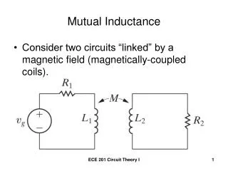
Definition: number of turns in coil 2 flux through one turn of coil 2 due to all N1 turns of coil 1 mutual inductance current in coil 1 cross-multiply • M21 contains all the • geometry • E2 is EMF induced • in 2 by 1 time derivative Another form of Faraday’s Law! The smaller coil radius determines how much flux is linked, so….. proof not obvious Mutual Inductance • Example: a pair of co-axial coils • di/dt in the first coil induces current in the • second coil, in addition to self-induced effects. • M21 depends on geometry only, as did L and C • Changingcurrent in primary (i1) creates varying • flux through coil 2 induced EMF in coil 2
Calculating the mutual inductance M Coil 1 (outer) is a short loop of N1 turns (not a long Solenoid) large coil 1 N1 turns radius R1 (primary) small coil 2 N2 turns radius R2 (secondary) Flux through inner flat coil 2 (one turn) depends on smaller area A2 & B1 Current in Loop 1 is changing: smaller radius (R2) determines the linkage Summarizing results for mutual inductance:
FIND INDUCED EMF IN INNER COIL DURING THIS PERIOD • coil diameter d = 2.1 cm = .021 m, Ain = p d2/4, short length • Nin = 130 turns = total number of turns in inner coil Direction: Induced B is parallel to Bouter which is decreasing Would the transformer work if we reverse the role of the coils? Air core Transformer Example: Concentric coils • OUTER COIL – IDEAL SOLENOID • coil diameter D = 3.2 cm • nout = 220 turns/cm = 22,000 turns/m • current iout falls smoothly from • 1.5 A to 0 in 25 ms • Field within outer coil:


![G5 - ELECTRICAL PRINCIPLES [3 exam questions - 3 groups]](https://cdn0.slideserve.com/382273/g5-electrical-principles-3-exam-questions-3-groups-dt.jpg)