Download
1 / 17
180 likes | 212 Views
Learn how to apply rectangular time pulses to an RC circuit using the 555 Timer. Understand duty cycle, charging, discharging, and timing aspects. Calculate pulse and space widths, frequency, and duty cycle in hands-on activities.

E N D
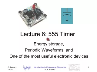
Rectangular Wave In the RC circuit from last week, we charged and discharged the capacitor by moving a switch. If you repeatedly switch between the battery and the short you are effectively applying a rectangular time pulse to the RC circuit.
Rectangular Waves- Reminder: Duty Cycle – ratio of pulse width to cycle time where PW= the pulse width of the circuit input T= the cycle time of the circuit input 3
Rectangular Wave Response The voltage across the capacitor will behave as below in response to such a wave:
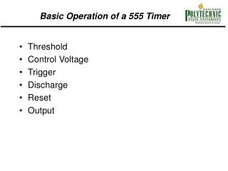
The 555 Compares the voltage at pin 6 to 2/3 Vcc The 555 Compares the voltage at pin 2 to 1/3 Vcc
Typical Wiring for a 555(astable mode) Notice that the boxed area is just an RC circuit
Current Flow During Capacitor Charging The capacitor charges via RA and RB until vc = 2/3 Vcc
Capacitor Voltage and Output Voltage Vcc 0 Red arrows indicate voltages during charging phases
Current Flow During Capacitor Discharging The capacitor discharges through just RB until vc = 1/3 Vcc
Capacitor Voltage and Output Voltage Vcc 0V Blue arrows indicate voltages during discharging phases
Timing During the charging phase, the capacitor voltage can be written as: During the discharging phase, the capacitor voltage can be written as:
In-Class Activity • How long does it take to:a) charge up from 1/3 Vcc to 2/3 Vcc? • Hint: Calculate time to reach each voltage first then subtract • b) discharge from 2/3 Vcc to 1/3 Vcc
555 Timing • Pulse width – capacitor charging time:PW = (RA + RB)C ln(2) sec • Space width – capacitor discharging time:SW = RB C ln(2) sec • Period = Pulse width + Space widthT = PW + SW = (RA + 2RB)C ln(2) sec • Frequency – 1/Periodf = 1/(RA + 2RB)C ln(2) = 1.443/(RA + 2RB)C Hz
555 Duty Cycle • Duty Cycle = 100 PW/T %or
In-Class Activity • In Multisim, build this 555 circuit, use RA = RB = 1kΩ and C = 1µF. • 555 can be found in Place-Mixed-Timer-LM555CM • What are the following: T, PW, SW, duty cycle, f? • Show them in hand calculations and record what you see on Multisim oscilloscope