Download
1 / 31
370 likes | 1.56k Views
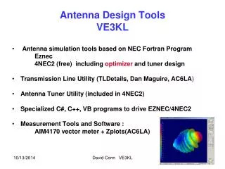
VE3KL Presentation 4NEC2 Antenna Simulator by Arie Voors. Based on the NEC2/4 Fortran Kernel Uses the classic Method of Moments Models radiating wires, loads, ground, sources…….more Four Editors with extensive Math capabilities Smith Charts Optimizer Extremely powerful graphics capabilities

E N D
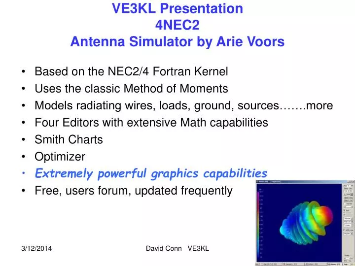
VE3KL Presentation4NEC2Antenna Simulator by Arie Voors • Based on the NEC2/4 Fortran Kernel • Uses the classic Method of Moments • Models radiating wires, loads, ground, sources…….more • Four Editors with extensive Math capabilities • Smith Charts • Optimizer • Extremely powerful graphics capabilities • Free, users forum, updated frequently David Conn VE3KL
Spherical Coordinate System Z θ Rx Antenna Elevation angle = 90 - θ Tx Antenna Y XY Horizontal Plane Z Vertical axis φ X φ is the horizontal azimuth angle Θ is the angle measured from vertical David Conn VE3KL
Method of Moments • A discrete numerical method • Divide wires into many segments…25 per wavelength • Apply Coulomb’s Law and match boundary conditions • Solve large matricies • EE Students usually solve the 3D Capacitor Problem David Conn VE3KL
3D Capacitor Example Divide plates into 14 segments Assume each plate has a point charge, ρi…not equal Apply a voltage V across the plates Write Coulombs Law for each charge > 14 by 14 Matrix Solve for charge by matrix inversion ρ1 ρ2 ρi V ρ14 Vj ρ1>ρ2 .. Charge piles up at edges David Conn VE3KL
4NEC2 Super Graphics Helix Antenna Vertically Oriented David Conn VE3KL
3D VE3XK 50 MHz Stack 50 MHz OMNI Source Side Along X Axis Right Hand Circular Polarization Shown David Conn VE3KL
2D VE3XK 50 MHz Stack 50 MHz OMNI Source Side Along X Axis Total Gain Shown David Conn VE3KL
4NEC2 3D Near Field David Conn VE3KL
4NEC2 Advanced Far Field Map θ High Gain φ David Conn VE3KL
4NEC2 Far Field Traditional Plot • Several Views • Vertical, Horizontal, Total • Circular Polarization • RHC, LHC, Total David Conn VE3KL
4NEC2 Several Views of Frequency Response David Conn VE3KL
4NEC2Smith Chart David Conn VE3KL
Matching David Conn VE3KL
4NEC2..The Big Gun (Optimization)Optimize (Tune) a 2 metre dipoleto 6 metres Adjust reactance to zero Vary Length Results L= 2.8 metres Xin = -0.13 Ohms David Conn VE3KL
An extremely complex and active field of study Local minimum vs. global minimum .. Optimizer gets trapped Poorly defined problem by the user .. Optimizer loops forever Type of Objective function minimum .. for science and math people good enough .. for engineers constrained values .. for engineers Can be difficult for beginners Example: An optimizer might set the antenna length to infinity! Optimization Issues David Conn VE3KL
Using the Editors Define the wires and axis Define the Voltage Sources Define the Ground Type if any Define R,L,C, Transmission Line components David Conn VE3KL
4NEC2Graphical Editor for Beginners David Conn VE3KL
4NEC2 NEC Editor to Describe the Antenna Note the use of Math Functions David Conn VE3KL
Simple Text Editor 'VE3XK OMNI 6 metres..stack SY height=3 'height in metres SY Freq=50.0 'freq in MHz SY B=0.3556 'metres SY C=0.8128 'metres SY D=0.29845 'metres SY rad=3.17e-3 'metres SY spacingWave=0.5 'spacing in wavelengths SY spacing=spacingWave*300/freq 'spacing in metres GW 1 21 -B 0 height B 0.00 heigh height+spacing rad GW 8 21 B C height+spacing B-D C Best for Computer Defined Antennas David Conn VE3KL
A New Windows Menu Type Editor Menu Bar on top allows user to define files rapidly Geometry Menu Open in this example David Conn VE3KL
Editing Big Antennas..500 SegmentsComplex Geometry • Use VB.Net or C#.net to drive the editors. 4NEC2 Text Editor VB.net Program Skew Planar Antenna David Conn VE3KL
Examples “Simple” 2m Dipole Free Space -L/2 L/2 X Axis Horizontal Plane Theta = 90 degrees Horizontally Polarized No Vertical Component (No surprises Here!) David Conn VE3KL
Examples “Simple” 2m Dipole Free Space -L/2 L/2 X Axis Horizontal Plane Theta = 90 degrees Horizontally Polarized No Vertical Component (No surprises Here!) David Conn VE3KL
Examples..Simple 2m Dipole -L/2 L/2 X Axis Horizontal Plane BLUE :Vertical E Field RED: Horizontal E Field Green: Total Field Theta = 45 degrees (Is it OK to say that a dipole is Horizontally Polarized?) David Conn VE3KL
50 MHz Horizontal OMNI Geometry Source side on X axis Horizontally Mounted Geometry Window David Conn VE3KL
50 MHz Horizontal OMNI Pattern Horizontal Plane Showing Circular Polarization Blue RHCP RED LHCP Green Total Nearly Omni Directional Circular Polarization on X axis Linear Polarization on Y axis Note the Red/Blue Cardioids θ = 55 Degrees David Conn VE3KL
50 MHz Vertical OMNI Pattern Height = 3 metres Vertical Plane Linearly Polarized Takeoff angle 30 deg Max Gain = 7.15 dBi θ = 90 Degrees David Conn VE3KL
50 MHz OMNI Stack Same Orientation as Single Element Height = 3 metres Spacing = 0.5 wavelengths David Conn VE3KL
50 MHz OMNI Stack Vertical Plane Same Orientation as Single Element Height = 3 metres Spacing = 0.5 wavelengths Gain Increased to 9.29 dBi Take off angle now 15 degrees Some high angle side lobes. David Conn VE3KL
50 MHz OMNI Stack Horizontal Plane Same Orientation as Single Element Height = 3 metres Spacing = 0.5 wavelengths Circularly Polarized along the X axis Θ = 73 degrees David Conn VE3KL
Summary • Uses NEC2 or NEC4 Engine • Contains an Optimizer • Outstanding Graphics capability • Uses four different editors • Many features not covered in this talk Fundamental Wave Reflection Talk Available 73 Dave VE3KL David Conn VE3KL