Download
1 / 64
650 likes | 1.13k Views
CS 537 Group 3 Report: Activity Diagrams and Observer Design Pattern. Anna Deghdzunyan Xuan Yang Keenan Knaur John Hurley. Part I: Activity Diagrams. Introduction(I). Activity diagrams describe procedural logic, business process, and workflow.

E N D
CS 537 Group 3 Report: Activity Diagrams and Observer Design Pattern Anna Deghdzunyan Xuan Yang Keenan Knaur John Hurley
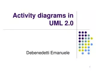
Introduction(I) • Activity diagrams describe procedural logic, business process, and workflow. • Activity diagrams focus on the action sequence of execution and the conditions that trigger or guard those actions. • Activity diagrams focus on the activity’s internal actions, not on the external interfaces
Introduction(II) • Activity diagrams have similarities to flowcharts • But flowcharts notation does not support parallel behavior. • Business managers may prefer activity diagrams over flowcharts, because they are more understandable for non-technical people. • An activity diagram is a special case of state chart diagram in which states are actions.
Introduction(III) • An activity diagram shows flow control within a system. Handle Incident Document Incident Archive Incident
Activity Diagram Elements • Initial node • Activity final node • Action • Flow/edge • Fork • Join • Decision • Merge • Synch
Basic Elements—Action(I) • Action in Activity Diagram Elements’ official UML name is action state. • Distinction between action and activity • Action state refers to it as action • Use term activity only refer to the whole task being modeled by the activity diagram
Basic Elements—Action(II) • The rounded rectangle represents an action that occurs. • E.g., Customer calls ticket office : A sample action that is part of an activity diagram Customer Calls Ticket Office
Basic Elements--Initial state • The filled circle is the staring point of the diagrams. An initial node isn’t required. The initial state shows the starting point for the action sequence within an activity diagram. First Action To DO
Basic Elements--Initial state(II) • Initial state can indicate only ONE action. Incorrect rendering of an initial state within an activity diagram. The initial state can indicate only ONE action Action 1 Action 2
Basic Elements—Flow/edge • The arrow on the diagram. There is a subtle difference between flows and edges.
Basic Elements—Final node • The filled circle with a border is the ending point. An activity diagram can have zero or more activity final nodes First Action To DO
Decision • A diamond with one flow entering and several leaving. [Drink contains alcohol] [else] Make Sure Customer Is At least 21 Years Old Customer Orders Drink Get Drink For Customer
Merge • A diamond with several flows entering and one leaving. [customer’s age < 21] [Drink contains alcohol] [customer’s age >= 21] [else] Tell Customer To Order A Non Alcoholic Drink Make Sure Customer Is At least 21 Years Old Customer Orders Drink Get Drink For Customer
Synch • A thick, solid line, allowing two or more action sequences to proceed in parallel Action 1
Fork • Synch with one flow going into it and several leaving it. • Denotes the beginning of parallel actions. Verify Order Products Are In Stock Receive Order Verify Customer Has Available Credit
Join • Synch with several flows entering and one leaving. • All incoming flows must reach it before processing may continue. This denotes the end of parallel processing. Verify Order Products Are In Stock Accept Order Verify Customer Has Available Credit
Signals • An Activity diagram can have a clearly defined start point, which corresponds to an invocation of a program or routine. • Activity diagram can also show response to signals. • A time signal occurs because of the passage of time (for example, each month end might trigger a signal.) • A real time signal indicates that the activity receives an event from an outside process. • The activity listens for those signals, and the diagram defines how the activity reacts.
Signals • Activity diagrams can show signals sent or received • For example, we can send a message and then wait for a reply before we can continue. • Basically, the signals are flow triggers. Send signal Time signal Accept signal
Flow • Connection between 2 actions • Simple flow - arrow - from a node to another • Flow with Exception
Flows (cont.) • Flow with objects • Flow with pins - similar to flows with objects - data needed and data produced
Flows (cont.) • Decision flows -labeled • Connectors - does the same job as a simple arrow
Tokens Tokens flow through the diagrams: • The initial node creates a token, executes, passes the token to the next • Fork produces a token on each of its outward flows. • On a join, as each inbound token arrives, nothing happens until all the tokens appear at the join; then a token is produced on the outward flow.
Join Specification • Boolean expression using the names of the incoming edges to specify the conditions under which the join will emit a token. • Evaluated whenever a new token is offered on any incoming edge. • Default - "and”
Expansion Region • Structured activity region that executes multiple times corresponding to elements of an input collection. • Example: The hotels may be booked independently and concurrently with each other and with booking the flight.
Advanced Notation • Conditional threads • Nested activity diagrams • Partitions
Conditional threads • One of a set of concurrent threads is conditional. • Example: Frequent-flyer member? Award the passenger frequent flyer miles.
Nested Activity Diagram • diagram refers to an external one that uses more abstraction
Partitions • The contents of an activity diagram may be organized into partitions • Does not have a formal semantic interpretation • May represent organizational unit
Dimensional Partition Dimensional Partition
Multidimensional Hierarchical Diagram Dimensional Partition
Activity vs. Sequence Diagrams • Activity diagrams give focus to the workflow • Sequence diagrams give focus to the handling of business entities. • Activity diagram with partitions focuses on how you divide responsibilities onto classes • The sequence diagram helps you understand how objects interact and in what sequence.
When to Use Activity Diagrams • Describe a behavior which contains parallel activities Or • Show how behaviors in several use-cases interact.
Specification standards • No need for documenting the Activity diagrams beyond diagram itself. • However, most UML tools provide in-built documentation capturing and printing capabilities for the Activity diagram and its elements.
Part II: Observer Design Pattern Also Known As: Dependents, Publish-Subscribe, and confusingly, Model-View
Introduction to Observer • A Gang of Four design pattern, one of the patterns discussed in Design Patterns: Elements of Reusable Object-Oriented Software by Erich Gamma, Richard Helm, Ralph Johnson, and John Vlissides. • Observer defines a one-to-many or many-to-many dependency between objects. • When the state of one object changes, then all the other objects that are dependent on that object are updated automatically. • Used for event handling where consistency between objects is necessary, e.g. Swing Framework for GUI development.
General Example • Suppose you have some data that can be displayed by a table, a bar graph or a pie chart. • Changes to the underlying data should be reflected in all three of the displays • This is where the Observer Design Pattern comes in handy.
Motivation for Using • Maintaining consistency between related objects is necessary when a system contains a collection of cooperating classes • This consistency shouldn’t be accomplished through tightly coupling the classes since this reduces the reusability of those tightly coupled classes. • Needs to be scalable. There should also be no limit on the number of objects that depend on one or more other objects.
Example of the Problem: • You are coding an app in which a weather station updates three objects, one that displays current conditions, one that calcs statistics over time (up to date), and one that makes a forecast. • Here is the obvious approach: public class WeatherData { [declarations and getters/setters omitted] public void measurements changed(){ float temp = getTemperature(); float humidity = getHumidity(); float pressure = getPressure(); currentConditionsDisplay.update(temp, humidity, pressure); statisticsDisplay.update(temp, humidity, pressure); forecastDisplay.update(temp, humidity, pressure); } } Freeman, Freeman, Sierra, and Bates, Head First Design Patterns,O’Reilly 2004
Problems With The Obvious Approach public void measurementsChanged(){ float temp = getTemperature(); float humidity = getHumidity(); float pressure = getPressure(); currentConditionsDisplay.update(temp, humidity, pressure); statisticsDisplay.update(temp, humidity, pressure); forecastDisplay.update(temp, humidity, pressure); } Problems: • Area that is likely to change is mixed with area that is not likely to change • update() calls are coded to concrete objects, not types • Need to change code if the subscribers change Observer addresses these problems
Three Major Aspects of Observer 1. The Subject, which is the object being observed 2. The Observer, which observes a Subject 3. Relationship between 1 and 2: attach/detach (or subscribe / unsubscribe) and update
Generalized Structure (cont.) • Subject • Interface for ConcreteSubjects • Requires implementations to provide at least the following methods: • subscribe / attach • unsubscribe / detach • notify all observers of state changes • ConcreteSubject • Implements the Subject interface • Maintains direct or indirect references to one or more ConcreteObservers • Keeps track of its own state • When its state changes it sends a notification to all of its Observers by calling their update() methods
Generalized Structure (cont.) • Observer • Interface for ConcreteObserver objects • Requires an update method • ConcreteObserver • This is the actual object that is observing the state of the ConcreteSubject. • The state that it maintains should always be consistent with the state of its Subject. • Implements update() method.
Two Ways to Implement Updates • The Push Model • Subject sends all of the necessary information about any of its changes to all the Observers. • Pushes information to the Observer as parameter with the update() method. • Requires assumptions about what the Observers need to know. • May need to allow for subscription to relevant changes only, but this adds complexity • The Pull Model • The Subject sends an indication to the Observer that a change has occurred. • Observers use public methods of Subject to query information they want • It is up to the Observer to pull all of the necessary information from the Subject in order to effect any relevant changes. • Subject requires fewer assumptions about what the observers want to know
General Implementation • Subjects can track Observers through ArrayLists or other data structures. • Observers can track multiple Subjects and get different data from each. • Pull model uses an update method that takes a reference to Subject as a parameter. • The Subject should trigger updates when its state changes.