Download
1 / 11
110 likes | 133 Views
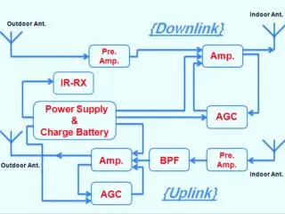
This study presents the proposal, circuit structures, and performance evaluation of integrated preamplifiers for GERDA. The focus is on the tested preamp chips, MOSFET structures, high voltage components, dynamic range, and energy sensitivity. Future developments involve optimization, testing with different capacitors, and miniaturized setup design.

E N D
Status of integrated preamplifiers for GERDA F. Zocca, A. Pullia, S.Riboldi, C. Cattadori GERDA meeting – MPI Heidelberg, Feb 20-22, 2006
Proposed circuit structure (from J. Gal*) *J. Gal et al. “Realization of charge sensitive preamplifiers using current feedback operational amplifier”, Nucl. Instrum. And Meth., Vol. A366, pp. 145-147, 1995
Tested preamp Test chip PREAMP 1 TEST struct MOSFETs PREAMP 1 pMOS + ext RF + ext bias Vmax = 550mV (50 Ohm) PREAMP 2 resistors PREAMP 2 pMOS + ext RF + int bias Vmax = 550mV (50 Ohm) MOSFETs PREAMP 3 TEST struct PREAMP 4 MOSFETs PREAMP 3 pMOS + reset pMOS + shaper MOSFETs PREAMP 4 pMOS + ext RF + ext bias Vmax = 2V (1 kOhm) HIGH VOLTAGE comp’s 3.3 mm CSP+OS simple CC=1.4pF CSP+OS simple CC=0.2pF CSP+OS simple CC=0.6pF CSP+OS simple CC=1pF CSP+OS simple CC=0pF CSP + OS simple CSP with new rail-to-rail output stage. Various comp cap’s CSP+OS cplx CC=1pF CSP+OS cplx CC=0pF CSP+OS cplx CC=2pF CSP+OS cplx CC=0.4pF CSP+OS cplx CC=1.4pF CSP + OS cplx CSP with new rail-to-rail output stage. Various comp cap’s OPAMP OPAMP OPAMP OPAMP 3.3 mm
Test chip with wire bondings in 68LCC package Setup for cryogenic test
Output stage & dynamic range The output stage must be able to drive a coax/twisted pair cable (or a 100 to 200 load) and must provide the largest negative voltage swing (hole signals) At T=300°K, with a negative power supply VEE = - 3V, the circuit can drive a 10m coaxial cable of 50 still providing a negative voltage swing of ~ 2.5V At T=77°K the negative swing reached is of ~ 2.4V CF = ~ 0.15 pF, Ctest = 1 pF Cdet = 15 pF Energy sensitivity (in Ge) at the preamp output = ~ 370 mV/MeV (~185 mV/MeV if 50 terminated) Inputdynamic range = ~6.5 MeV
Rise time at T = 300 °K driving a 50 coaxial cable of different lengths ~ 13 ns with ~1m cable ~ 15 ns with ~10m cable
Rise time at T = 77 °K driving a ~2m coaxial cable (50) 7.8 ns with no BW limit A fast rise time of ~ 8 ns to ~ 13 ns has been obtained but a little overshoot has still to be eliminated by a low-pass filter or by reducing the preamp bandwidth a little bit 13 ns with BW limit (equivalent to Anti-Aliasing filter)
Decay time constant ~ 200 s both at room temperature and in liquid nitrogen T = 300 °K CF = ~ 0.15 pF RF = 1.2 G ~200s T = 77 °K ~200s
Noise measurements Cdet = 15 pF At T =77 °K the substantial increase of the white series noise is mainly due to the decrease of the JFET tranconductance
Future developments • Optimization of tested preamplifier • Tests with different values of Cdet and with values of CF ranging from 0.2 to 1 pF • Tests of more preamplifiers (with different values of compensation capacitance) • Design and test of a miniaturized setup • Tests with different cable types and lengths Activity schedule • March-June 2006: tests/optimization of existing chip. Design/realization of miniaturized PCB. Design of improved new chip. • June-September 2006: realization of new chip / tests of old chip (continued) • September-December 2006: tests of new chip