Download
1 / 12
160 likes | 438 Views
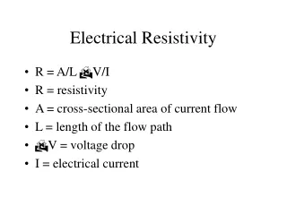
Resistivity Sounding . West Tahoe Fault & UNR North Parking Lot MiniRes L&R Instrument. Objectives. Use resistivity to obtain a profile across the West Tahoe Fault Constrain the source of poor data. IP & Earth Resistivity Meter ( MiniRes ). MEASURES: Earth resistivity

E N D
Resistivity Sounding WestTahoe Fault & UNR North Parking Lot MiniRes L&R Instrument
Objectives • Use resistivity to obtain a profile across the West Tahoe Fault • Constrain the source of poor data
IP & Earth Resistivity Meter(MiniRes) • MEASURES: • Earth resistivity • Induced polarization • USES: • Ground Water Exploration • Geotechnical Engineering • Locating & Categorize Fractures • Archaeology Water Well Fractures • Contaminated plumes • Geologic Structures • Hydrogeologic Characterization • Surface Resistivity for M.T. • Agricultural Applications • Corrosive Soil Identification • Electrical Grounding
Base of Echo Pass near South Lake Tahoe • Centered on LIDAR image of the fault trace • Site conditions were snowy and wet Echo Pass
Echo Pass Objectives • To obtain a profile across the fault trace • Soundings parallel and perpendicular to fault trace • Used Wenner Array to collect four soundings • Resistivity values were unrealistically high
UNR North Parking Lot • North parking lot near medical center • Site conditions were favorable except for nearby fence & culvert
UNR Results • Used Wenner Array • Complex Profile • Simple Profile • Instrument is Functional
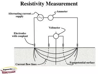
Taking a Typical Field Reading • Four electrodes are used for field readings and they are placed along a straight line, usually at uniform intervals (A-Spacing’s). • The instrument (MiniRes) is placed near the middle of the line. • The far two electrodes are used to put electric current into the earth. • The middle two electrodes are used to measure the voltage in the earth. • The far electrodes are connected to the MiniRes with cables. • The cables are connected to the C+ and the C- binding posts on the right side of the MiniRes. • The middle two electrodes are connected to the P+ and the P- binding posts on the left side of the MiniRes. • Be sure the C+ and P+ cables go to the electrodes on the same side of the MiniRes.
This is the most common method of sounding in the United States and has the greatest signal to noise ratio and is least susceptible to near-surface homogeneities. The four electrodes are in a straight line and are at uniform separation. The separation between adjacent electrodes is designated “a”. Wenner Array
This is the most common method of sounding in Europe and is common in the United States. It saves moving the potential electrodes every time the current electrodes are moved. The electrodes are in a straight line and like the Wenner array, the outer electrodes are the current electrodes and the inner electrodes are the potential electrodes. The potential electrodes, usually designated M and N, should never be separated by more that one-fifth the separation between the current electrodes. The current electrodes are usually designated A and B. Schlumberger Array