Download
1 / 27
280 likes | 315 Views
Dive into the detailed design and characterization of a 64-QAM communications system, covering source coding, modulation, channel modeling, demodulation, decoding, and BER measurements. Explore the intricacies of baseband waveforms and optimize bandwidth efficiency to achieve reliable data transmission in communication systems.

E N D
64-QAM Communications System Design and Characterization Project #1 EE283 daeik.kim@duke.edu
What you need to do (red) • Assignments: • 1. Data Source (0) • Propose a data source that you will use for your communication system. Discuss the randomness of data. • 2. 64-QAM Memoryless Channel Coder (25) • Design a channel coder with a code rate 1. The designed data source feeds the channel coder. The coder outputs are 64-QAM in-phase and quadrature-phase data. For example, with 6-bits taken from data source, an in-phase and a quadrature-phase amplitudes are produced. • 3. QAM Base Band Modulation (25) • Design a QAM modulator. Modulator inputs are the output of 64-QAM channel coder and the modulation frequency, etc. The output is a modulated QAM waveform. Show unit in-phase, unit quadrature-phase, and random data waveforms in a fine time resolution (for readability). • 4. Channel Modeling (0) • Design a channel module that adds Gaussian noise to the modulated data with a given noise intensity. Show a 64-QAM eye diagram. • 5. QAM Base Band Demodulation (25) • Design a QAM demodulator. Assume that full phase information is given and the phase is locked. The demodulator outputs are in-phase and quadrature-phase amplitudes. Show a demodulated 64-QAM constellation with noise. • 6. 64-QAM Channel Decoder (25) • Design a QAM decoder that performs the inverse of the designed 64-QAM channel coder. • 7. BER Measurements (0) • Design a module calculates bit-error-rate with the original data source and the decoded data stream. Discuss how many measurements are required to get 95% or 99% confidence. Make a plot of BER vs SNR. All the numbers, such as signal power and noise power, must be obtained from simulation. • 8. Bandwidth Efficiency (0) • Calculate the bandwidth efficiency with a given BER. All the numbers, such as bandwidth must be obtained from simulation. Discuss the definition of bandwidth of your baseband waveform.
Outline • 64-QAM communications system • Testing and measurements • Tools, grading, etc.
64-QAM Communications System Design • Signal source and source coding • Channel coding • Baseband modulation • Channel modeling • Baseband demodulation • Channel decoding • Source decoding and signal sink Simplified 64-QAM communications system
Signal source and source coding • Ideal source coded data • “Random” • Memoryless source • Equiprobable • Spectrum and autocorrelation • A randomly generated data • What if the data is not random?
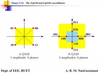
64-QAM Channel Coding • 2^6=64 • Use rate 1 code • Map a sequence of 6-bits to 64 symbols • Symbol error • Bit error An example of 16-QAM mapping
Baseband Modulation (1) In-phase Quadrature-phase
Baseband Modulation (2) (-1,-1) (-1,+1) (+1,-1) (+1,+1)
Baseband Modulation (3) 64-QAM waveform with random data
Baseband Modulation (4) • Sampling of waveform • Minimum samples per symbol • Number of waves per symbol • Orthogonal signals • [1 1] vs. [1 -1] • [1 0 -1 0] vs. [0 1 0 -1]
Channel Modeling • Noise • Additive • White • Gaussian Contaminated baseband signal
Baseband Demodulation • Correlative receiver • Matched filter receiver 64-QAM Demodulated Data
Clock Recovery and Phase Locking • Clock recovery from baseband signal • Phase locking • Maintain constant clock and locked phase • Clock synchronization pilot signal • Assume perfect clock recovery and phase locking 64-QAM Demodulated with perfect phase and 2.5% phase lag
Channel Decoding and Signal Sink • Channel Decoding • Inverse of channel coding • Simple hard decision • Signal Sink • Compare received and decoded data with signal source
Testing and Measurements • Obtain • 64-QAM waveform • Eye diagram • Bit error rate • Bandwidth efficiency
Symbol / Bit Error Rate • S/BER=Symbol or Bit Error / Tx-Rx Bits • How many symbols/bits to test for a given BER • How many measurements for a given BER • 95% or 99% confidence interval • t-test BER SNR(dB) An example of 64-QAM BER plot
Channel Bandwidth • 3-dB bandwidth • Or your definition and justification Modulated 64-QAM spectrum
Theory vs. Practice • Given BER plot vs. experimented BER plot • Given bandwidth efficiency vs. experimented bandwidth efficiency
Tools • Any tools supported by ECE • MATLAB recommended • C, C++, Java, Visual Basic, Perl, PHP… • Simulink ?
>> A=[0 1 2; 3 4 5] A = 0 1 2 3 4 5 >> A=(0:0.2:1)' A = 0 0.2000 0.4000 0.6000 0.8000 1.0000 >> plot(A,cos(2*pi*A)) >> ta=1:-0.01:0; >> tb=(0:.01:1)'; >> ta+tb'; >> ta'.*tb; >> ta.^2; >> ta(1:10)=tb(11:20)’; >> help >> help elfun >> lookfor signal >> demo MATLAB (1)
Flow control for N=1:10, ---; end if <true/false>, ---; else, ---; end switch <var> case <cond1> ---; case <cond2> ---; otherwise ---; end Function call function [Y,Z]=Name(X) %Name.m %Usage %function Y=Name(X) <Commands> Y=1; Z=2; return; >> Y=Name(1); >> [Y,Z]=Name(2); MATLAB (2)
Useful functions mean sum size length zeros ones rand randn figure plot xlabel ylabel title semilogx semilogy loglog log10 log i j pi round ceil floor sgn fft spectrum Matlab (3)
MATLAB (4) • Vector operation vs. scalar operation >> A=1:1e4; MeanSquare=mean(A.^2); >> A=1:1e8; • Vector preparation before usage >> A=zeros(1,100); for k=1:100, A(k)=k+1; end >> for k=1:100, A(k)=k+1; end >> A=[]; for k=1:100, A=[A k+1]; end
Things to submit • Documentation • An electronic copy in PDF of PS format • IEEE journal format • Scripts execution methods • Scripts • “tar”ed and compressed scripts • “lastname_firstname.tar.gz” or “.tar.Z” • All scripts should be in “lastname_firstname” directory • Script execution must be one-step, i.e. ‘filename’+’enter’
Deadline • Submit to dkim@ee.duke.edu • 9/24 (Fri) 11:00pm • Time marked by the recipient server (ee.duke.edu) • Penalty for late submission without permission (-20% per a day) • No virus (frown per a virus)