Download
1 / 21
210 likes | 233 Views
This document outlines the vacuum system at the Interaction Region (IR) for the KEKB accelerator, focusing on pressures, remedies for heating issues, and maintaining optimal performance. It details the materials used, vacuum pumps, gauges, and the behavior of pressures in different sections. Remedies for heating components like gate valves, stoppers, and RF shields are discussed, along with future measures such as new RF shield structures and HOM absorbers. The text addresses specific issues like heating by HOM sources and proposes solutions like installing HOM absorber chambers. The current status, pressure management strategies, and references are also provided for a comprehensive understanding of the vacuum system at the IR.

E N D
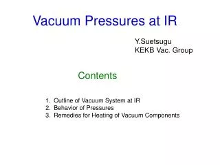
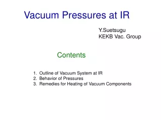
Vacuum Pressures at IR Y.Suetsugu KEKB Vac. Group Contents • Outline of Vacuum System at IR • Behavior of Pressures • Remedies for Heating of Vacuum Components
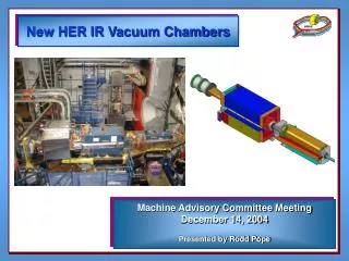
Vacuum System at IR • Here IR (Interaction region) means the straight section in ±~100 m from IP (Interaction Point), especially upstream side of each ring. • Material of beam duct: OFC (Oxygen Free Copper) for most part (both rings). Aluminum alloy for complicated chamber just near to IP. [Aluminum Alloy] [OFC]
Vacuum System at IR • Vacuum pump: Main pump = NEG (st707) : almost every 1 m (0.2 m3/s), Auxiliary pump = Ion pumps : almost every 10 m (0.2 m3/s). In average, about 0.7 m3/s/m just after an activation of NEG. NEG cartridge (arc section) NEG module (just near to IP)
Vacuum System at IR • Vacuum gauge = CCG (Cold Cathode Gauge) just above ion pumps (every ~10 m). A small dipole magnet (permanent magnet) is attached at the neck of gauge port to eliminate photoelectron effect. Without Manget CCG ~100 G
Vacuum System at IR • Location of Gauges and Pumps near to IP HER LER D01_H02 D02_H23 IP D01_H02A D01_H01A D02_H23A (D02_H24) [Inside of BELLE Solenoid] Integrated NEG Integrated NEG 0 10 m 5 m
Vacuum System at IR • HER Upstream Side (straight section, ~100 m) • Straight : No bending magnet • Gauges: every ~10 m D01_H01A D01_H03 D01_H02A D01_H04 D01_H05 IP GV GV D01_H06 D01_H7 D01_H8 GV BS D01_H10 D01_H09 D01_H11 HER
Vacuum System at IR • LER Upstream Side (straight section, ~100 m) • Local correction region: 13 bending magnets • Gauges: every ~10 m LER D02_L16 D02_L17 GV BS GV D02_L19 D02_L20 D02_L18 IP GV D02_L21 D02_L22 D02_H23A D02_L23 D02_L24
Behavior of Pressure • HER_1 Three days including several beam Injections. D01_H04 D01_H03 D01_H02A D01_H01A IP D01_H06 D01_H7 D01_H8 2x10⁻⁷ Pa Heat Source = Gate Valve P Big BG Source 0 0 1.4 A Ib
Behavior of Pressure • HER_2 Three days including several beam injections. Gate Valve D01_H7 D01_H8 Gate Valve D01_H06 D01_H09 Heat Source = HOM Absorber, Taper D01_H10 D01_H11 Heat Source = Stopper (~ Gate Valve)
Behavior of Pressure Three days including several beam aborts. • LER_1 ? (NEG?) D02_L20 D02_L18 D02_L19 IP D02_L21 D02_H23A D02_L23 Heat Source = Gate Valve D02_L22 D02_L24 3x10⁻⁷ Pa P Heating +NEG? Multipactoring? 0 0 2.0 A Ib
Behavior of Pressure Three days including several beam aborts. • LER_2 Heat Source = Taper Heat Source = Stopper D02_L16 D02_L17 D02_L15 Gate Valve Gate Valve D02_L19 D02_L20 D02_L18 ? (NEG?)
Present Status • The pressures near to IP is <1x10⁻⁷ Pa for HER and ~2x10⁻⁷ Pa for LER at the maximum operation current. • The pressures at upstream side of IP (IR) is almost less than 1x10⁻⁷ Pa,but affected by the heating of components, such as gate valves, stoppers, HOM absorbers and NEG(?). • The same harmful effect by heating can be seen widely in arc sections too. A major problem for further improvement of pressure.
Remedies to heating • Main reason of the heating is HOM. • Heating of Gate Valves, Stoppers and Bellows • Finger-type RF shield is not enough for high current • TE mode can easily coupled to modes outside • Tentative measure = Cooling from outside [Gate Valve] symptomatic therapy [Bellows]
Remedies to heating • Future (more essential) measure • Proposal of a New RF-shield structure • Comb-type RF-shield • 6 circular-type and 1 race-track-type has been installed in LER, and showed good results. • Application to gate valves are now planed and a test model will be installed in the ring this winter.
Remedies to heating • Heating of NEG • Gas desorption from heated NEG had been observed near collimators. • HOM (TE-mode) intruded through a grid into pump port. • Tentative measure = use a special gasket f = 6 mm t = 2 mm Cu Lead to heating of other components • HOM absorber were installed finally.
Remedies to heating • Heating by other HOM sources, such as collimators or tapers. • Install HOM absorber chamber • Example installed near collimators • HOM absorber = SiC SiC Slot Wing SiC Beam Chamber Require Space ! How about IR?
Summary • The pressures at upstream side of IP is almost less than 1x10⁻⁷ Pa, but also affected by the heating of components, such as gate valves, stoppers, tapers, NEG and HOM absorbers. • The problem had been solved accordingly so far. But, essential (drastic) remedies, such as employing new RF-shield or installing HOM absorbers, will be required for future high current operation. • Improvement of pumping speeds and cooling capacity are of course important.
Present Status • Typical Run(11/09/2004) Beam Current 1.2A x 1.6 A Lifetime 230, 180 min Ave. Pressure 10-7 Pa Luminosity ~1.1x1034cm-2/s Beam currents are usually limited by any problems in vacuum components
Present Status (If S = 0.3 m3/s/m) • Vacuum Aging (arc section, -2004/10/31) • DP/DI : 1x10⁻⁷ Pa/A • Photo-desorption coefficient,h : ~ 3x10⁻⁷ mole./photon • Effect of photoelectrons were eliminated by magnets. • HER seems to be effected by heating of components. [LER] [HER] DP/DI DP/DI Max. I Max. I [Pa/mA] [Pa/mA] PM PM [mA] [mA] (Corrected) [PM]:Set permanent magnets to every gauge port
Present Status Just near to GV! • Vacuum pressures in HER (~300 gauges) (ARES) (ARES) (SCC) (SCC)