Download
1 / 10
100 likes | 112 Views
Explore the methods of projection in computer graphics, including perspective and parallel projection. Learn about perspective foreshortening, vanishing points, and anomalies. Discover orthographic, axonometric, and oblique projections.

E N D
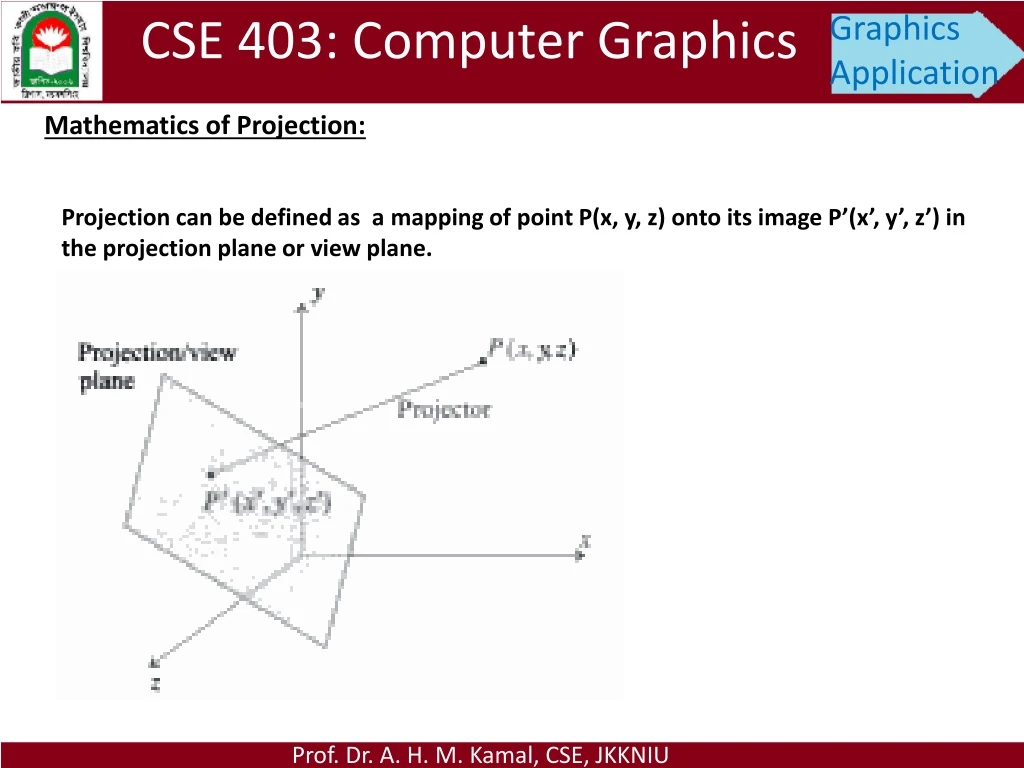
CSE 403: Computer Graphics Graphics Application Mathematics of Projection: Projection can be defined as a mapping of point P(x, y, z) onto its image P’(x’, y’, z’) in the projection plane or view plane. Prof. Dr. A. H. M. Kamal, CSE, JKKNIU
CSE 403: Computer Graphics Graphics Application Mathematics of Projection: Methods of Projection a. Perspective b. Parallel Prof. Dr. A. H. M. Kamal, CSE, JKKNIU
CSE 403: Computer Graphics Graphics Application Mathematics of Projection: Perspective Foreshortening: is the illusion that object and lengths appear smaller as their distance from the centre of projection increases. Perspective Vanishing: The illusion that certain set of parallel lines appear to meet at a point called vanishing point. Methods of Projection a. Perspective b. Parallel Prof. Dr. A. H. M. Kamal, CSE, JKKNIU
CSE 403: Computer Graphics Graphics Application Mathematics of Projection: Perspective Projection The object point P (x, y, z) in the world coordinates and the projected point P’(x’, y’, z’) in the image point coordinate. d: distance between view plane and centre of projection. Prof. Dr. A. H. M. Kamal, CSE, JKKNIU
CSE 403: Computer Graphics Graphics Application Mathematics of Projection: Perspective Anomalies: Perspective Foreshortening: The farer an object is from the centre of projection, the smaller it appears. Vanishing Points: If the projection of lines are not perpendicular to view plane, lines appear to meet at some points on the view plane. It creates illusion problem. For this, two rail-lines appear to meet at a point at a distance place. View Confusion: Object behind the centre of projection are projected upside down and backward onto the plane Topological Distortion: Consider all points on a plan. If these points are parallel to view plane and passes through the COP, then these points are projected to a broken line of infinite degree. Camera Focusing Glass Rail line Prof. Dr. A. H. M. Kamal, CSE, JKKNIU
CSE 403: Computer Graphics Graphics Application Mathematics of Projection: Parallel Projection: Prof. Dr. A. H. M. Kamal, CSE, JKKNIU
CSE 403: Computer Graphics Graphics Application Mathematics of Projection: Parallel Projection: • Orthographic Projection: The directions of the projections are perpendicular to the view plane. • Kinds: • Front view, • Top view, • Side view and • Axonometric projection Prof. Dr. A. H. M. Kamal, CSE, JKKNIU
CSE 403: Computer Graphics Graphics Application Mathematics of Projection: Parallel Projection: • Orthographic Projection: The directions of the projections are perpendicular to the view plane. • Kinds: • Front view, • Top view, • Side view and • Axonometric projection Axonometric: These projections are those in which the direction of projection is not parallel to any of the three principal axis. Orthographic projections that show more than one face of an object are called axonometric orthographic projections. Prof. Dr. A. H. M. Kamal, CSE, JKKNIU
CSE 403: Computer Graphics Graphics Application Mathematics of Projection: Parallel Projection: Some common subcategories of Orthographic Axonometric projection. Isometric:-The direction of angels with all of the three principle axes are equal. Di-metric:- The direction of angels with two of the three principleaxes are equal. Tri-metric:- The direction of angels with all of the three principleaxes are unequal. Prof. Dr. A. H. M. Kamal, CSE, JKKNIU
CSE 403: Computer Graphics Graphics Application Mathematics of Projection: Parallel Projection: • Oblique Projection: The directions of the projections are not perpendicular to the view plane. Common Kinds: • Cavalier and • Cabinet Cavalier:- All lines perpendicular to the projection plane are projected with no change in length. Cabinet:- The direction of projections is chosen so that lines perpendicular to the projection plane are foreshortening by half their lengths. It results in foreshortening the z-axis. Self Study: Solved Problem 7.1 and 7.2 Prof. Dr. A. H. M. Kamal, CSE, JKKNIU