Download
1 / 114
1.14k likes | 1.35k Views
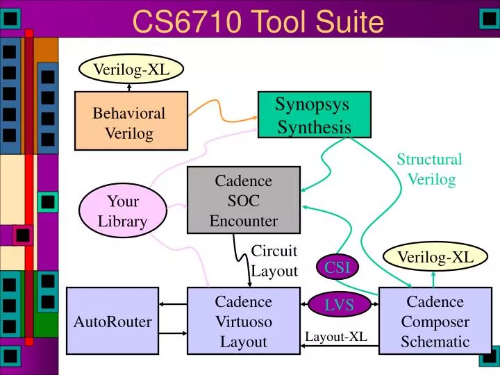
CS6710 Tool Suite. Verilog-XL. Synopsys Synthesis. Behavioral Verilog. Structural Verilog. Cadence SOC Encounter. Your Library. Circuit Layout. Verilog-XL. CSI. AutoRouter. Cadence Virtuoso Layout. Cadence Composer Schematic. LVS. Layout-XL. Verilog is the Key Tool.

E N D
CS6710 Tool Suite Verilog-XL Synopsys Synthesis Behavioral Verilog Structural Verilog CadenceSOCEncounter Your Library Circuit Layout Verilog-XL CSI AutoRouter CadenceVirtuosoLayout CadenceComposerSchematic LVS Layout-XL
Verilog is the Key Tool • Behavioral Verilog is synthesized into Structural Verilog • Structural Verilog represents net-lists • From Behavioral • From Schematics • From makeMem • High-level (Synthesizer will flatten these) • Verilog is used for testing all designs • Behavioral & Structural & Schematic & High-level • Verilog-XL, NC_Verilog, vcs
Verilog can have split personality • Hardware Description Language (HDL) • Reliably & Readably • Create hardware • Document hardware • The wire-list function fits into HDL • Testbench creation language • Create external test environment • Time & Voltage • Files & messages • Are these two tasks • Related? • Compatible?
Verilog as HDL • Want high level modeling • unification at all levels • from fast functional simulation, accurate device simulation • support simulation and formal verification • How could we do this? • behavioral model mapped to transistors • pragmas: throughput, latency, cycle time, power… • Reality • we rely on designers to do most of these xforms • therefore: • different algorithms => try before you buy… • use only a subset of the language. • RTL and schematic design used to support Verilog • System-C and other HLD models for co-simulation, etc.
Synthesis This lecture is only about synthesis...
Quick Review Module name (args…);begin parameter ...; // define parameters input …;// define inputsoutput …;// define outputswire … ; // internal wiresreg …;// internal regs, possibly output // the parts of the module body are // executed concurrently <continuous assignments> <always blocks> endmodule
Quick Review • Continuous assignments to wire vars • assign variable = exp; • Results in combinational logic • Procedural assignment to reg vars • Always inside procedural blocks (always blocks in particular for synthesis) • blocking • variable = exp; • non-blocking • variable <= exp; • Can result in combinational or sequential logic
Verilog Description Styles • Verilog supports a variety of description styles • Structural • explicit structure of the circuit • e.g., each logic gate instantiated and connected to others • Behavioral • program describes input/output behavior of circuit • many structural implementations could have same behavior • e.g., different implementation of one Boolean function
Synthesis: Data Types • Possible Values (wire and reg): • 0: logic 0, false • 1: logic 1, true • Z: High impedance • Digital Hardware • The perspective of Verilog • Either logic (gates) • Or storage (registers & latches) • Verilog has two relevant data types • wire • reg
Synthesis: Data Types • Register declarations • reg a; \\ a scalar register • reg [3:0] b; \\ a 4-bit vector register • output g; \\ an output can be a reg reg g; • output reg g; \\ Verilog 2001 syntax • Wire declarations • wire d; \\ a scalar wire • wire [3:0] e; \\ a 4-bit vector wire • output f; \\ an output can be a wire
Parameters • Used to define constants • parameter size = 16, foo = 8; • wire [size-1:0] bus; \\ defines a 15:0 bus
Synthesis: Assign Statement • The assign statement creates combinational logic • assign LHS = expression; • LHS can only be wire type • expression can contain either wire or reg type mixed with operators • wire a,c; reg b; output out; assign a = b & c; assign out = ~(a & b);\\ output as wire • wire [15:0] sum, a, b; wire cin, cout; assign {cout,sum} = a + b + cin;
Synthesis: Basic Operators • Bit-Wise Logical • ~ (not), & (and), | (or), ^ (xor), ^~ or ~^ (xnor) • Simple Arithmetic Operators • Binary: +, - • Unary: - • Negative numbers stored as 2’s complement • Relational Operators • <, >, <=, >=, ==, != • Logical Operators • ! (not), && (and), || (or) assign a = (b > ‘b0110) && (c <= 4’d5); assign a = (b > ‘b0110) && !(c > 4’d5);
Synthesis: Operand Length • When operands are of unequal bit length, the shorter operator is sign-extended to the most significant bit position wire [3:0] sum, a, b; wire cin, cout, d, e, f, g; assign sum = f & a; assign sum = f | a; assign sum = {d, e, f, g} & a; assign sum = {4{f}} | b; assign sum = {4{f == g}} & (a + b); assign sum[0] = g & a[2]; assign sum[2:0] = {3{g}} & a[3:1];
Synthesis: More Operators • Concatenation • {a,b} {4{a==b}} { a,b,4’b1001,{4{a==b}} } • Shift (logical shift) • << left shift • >> right shift assign a = b >> 2; // shift right 2, division by 4 assign a = b << 1; // shift left 1, multiply by 2 • Arithmetic assign a = b * c; // multiply b times c assign a = b * ‘d2; // multiply b times constant (=2) assign a = b / ‘b10; // divide by 2 (constant only) assign a = b % ‘h3; // b modulo 3 (constant only)
Synthesis: Operand Length • Operator length is set to the longest member (both RHS & LHS are considered). Be careful. wire [3:0] sum, a, b; wire cin, cout, d, e, f, g; wire[4:0]sum1; assign {cout,sum} = a + b + cin; assign {cout,sum} = a + b + {4’b0,cin}; assign sum1 = a + b; assign sum = (a + b) >> 1; // what is wrong?
Synthesis: Extra Operators • Funky Conditional • cond_exp ? true_expr : false_expr wire [3:0] a,b,c; wire d; assign a = (b == c) ? (c + ‘d1): ‘o5; // good luck • Reduction Logical • Named for impact on your recreational time • Unary operators that perform bit-wise operations on a single operand, reduce it to one bit • &, ~&, |, ~|, ^, ~^, ^~ assign d = &a || ~^b ^ ^~c;
Synthesis: Assign Statement • The assign statement is sufficient to create all combinational logic • What about this: assign a = ~(b & c); assign c = ~(d & a);
Synthesis: Assign Statement • The assign statement is sufficient to create all combinational logic • What about this: assign a = ~(b & c); assign c = ~(d & a); B A C D
Simple Behavioral Module // Behavioral model of NAND gatemodule NAND (out, in1, in2); output out; input in1, in2; assign out = ~(in1 & in2);endmodule
Simple Behavioral Module // Behavioral model of NAND gate module NAND (out, in1, in2); output out; input in1, in2;// Uses Verilog builtin nand function // syntax is func id (args); nand i0(out, in1, in2);endmodule
Simple Behavioral Module // Behavioral model of NAND gate module NAND (out, in1, in2); output out; input in1, in2; nand _i0(out, in1, in2);// include specify block for timingspecify (in1 => out) = (1.0, 1.0); (in2 => out) = (1.0, 1.0); endspecify endmodule
Simple Structural Module // Structural Module for NAND gatemodule NAND (out, in1, in2); output out; input in1, in2; wire w1;// call existing modules by name // module-name ID (signal-list); AND2X1 u1(w1, in1, in2); INVX1 u2(out,w1);endmodule
Simple Structural Module // Structural Module for NAND gatemodule NAND (out, in1, in2); output out; input in1, in2; wire w1;// call existing modules by name // module-name ID (signal-list); // best to connect ports by name... AND2X1 u1(.Q(w1), .A(in1), .B(in2)); INVX1 u2(.A(w1), .Q(out));endmodule
Procedural Assignment • Assigns values to register types • They involve data storage • The register holds the value until the next procedural assignment to that variable • The occur only within procedural blocks • initial and always • initial is NOT supported for synthesis! • They are triggered when the flow of execution reaches them
Always Blocks • When is an always block executed? • always • Starts at time 0 • always @(a or b or c) • Whenever there is a change on a, b, or c • Used to describe combinational logic • always @(posedge foo) • Whenever foo goes from low to high • Used to describe sequential logic • always @(negedge bar) • Whenever bar goes from high to low
Synthesis: Always Statement • The always statement creates… • always @sensitivity LHS = expression; • @sensitivity controls when • LHS can only be reg type • expression can contain either wire or reg type mixed with operators • Logic reg c, b; wire a; always @(a, b) c = ~(a & b); always @* c = ~(a & b); • Storage reg Q; wire clk; always @(posedge clk) Q <= D;
Procedural Control Statements • Conditional Statement • if ( <expression> ) <statement> • if ( <expression> ) <statement> else <statement> • “else” is always associated with the closest previous if that lacks an else. • You can use begin-end blocks to make it more clear • if (index >0) if (rega > regb) result = rega; else result = regb;
Multi-Way Decisions • Standard if-else-if syntax If (<expression>)<statement>else if (<expression>)<statement>else if (<expression>)<statement>else<statement>
Procedural NAND gate // Procedural model of NAND gatemodule NAND (out, in1, in2); output out; reg out; input in1, in2;// always executes when in1 or in2 // change value always @(in1 or in2) begin out = ~(in1 & in2); endendmodule
Procedural NAND gate // Procedural model of NAND gatemodule NAND (out, in1, in2); output out; reg out; input in1, in2;// always executes when in1 or in2 // change value always @(in1 or in2) begin out <= ~(in1 & in2); endendmodule Is out combinational?
Synthesis: NAND gate input in1, in2; reg n1, n2; // is this a flip-flop? wire n3, n4; always @(in1 or in2) n1 = ~(in1 & in2); always @* n2 = ~(in1 & in2); assign n3 = ~(in1 & in2); nand u1(n4, in1, in2); • Notice always block for combinational logic • Full sensitivity list, but @* works (2001 syntax?) • Can then use the always goodies • Is this a good coding style?
Procedural Assignments • Assigns values to reg types • Only useable inside a procedural block Usually synthesizes to a register • But, under the right conditions, can also result in combinational circuits • Blocking procedural assignment • LHS = timing-control expa = #10 1; • Must be executed before any assignments that follow (timing control is optional) • Assignments proceed in order even if no timing is given • Non-Blocking procedural assignment • LHS <= timing-control expb <= 2; • Evaluated simultaneously when block starts • Assignment occurs at the end of the (optional) time-control
Procedural Synthesis • Synthesis ignores all that timing stuff • So, what does it mean to have blocking vs. non-blocking assignment for synthesis? How does this relate to reg? • beginbeginA=B;A<=B;B=A;B<=A;end end • begin beginA=Y; A<=Y;B=A; B<=A;end end ? ?
Synthesized Circuits D D D D Q Q Q Q clk clk clk clk A Y • begin A = Y; B = A;end • begin A <= Y; B <= A; end • begin B = A; A = Y; end A B B A Y B A B
Synthesized Circuits D D D D Q Q Q Q clk clk clk clk always @(posedge clk) begin A = Y; B = A; end always @(posedge clk) begin B = A; A = Y; end always @(posedge clk) begin A <= Y; B <= A; end always @(posedge clk) begin B <= A; A <= Y end A Y A B B clk A Y B A B clk
Assignments and Synthesis • Note that different circuit structures result from different types of procedural assignments • Therefore you can’t mix assignment types in the same always block • And you can’t use different assignment types to assign the same register either • Non-blocking is often a better model for hardware • Real hardware is often concurrent…
Comparator Example • Using continuous assignment • Concurrent execution of assignments Module comp (a, b, Cgt, Clt, Cne);parameter n = 4;input [n-1:0] a, b;output Cgt, Clt, Cne;assign Cgt = (a > b); assign Clt = (a < b); assign Cne = (a != b);endmodule
Comparator Example • Using procedural assignment • Non-blocking assignment implies concurrent Module comp (a, b, Cgt, Clt, Cne);parameter n = 4;input [n-1:0] a, b;output Cgt, Clt, Cne;reg Cgt, Clt, Cne;always @(a or b) begin Cgt <= (a > b); Clt <= (a < b); Cne <= (a != b); endendmodule
Modeling a Flip Flop • Use an always block to wait for clock edge Module dff (clk, d, q); input clk, d; output q; reg q;always @(posedge clk) q = d;endmodule
Synthesis: Always Statement • This is a simple D Flip-Flop reg Q; always @(posedge clk) Q <= D; • @(posedge clk) is the sensitivity list • The Q <= D; is the block part • The block part is always “entered” whenever the sensitivity list becomes true (positive edge of clk) • The LHS of the <= must be of data type reg • The RHS of the <= may use reg or wire
Synthesis: Always Statement • This is an asynchronous clear D Flip-Flop reg Q; always @(posedge clk, posedge rst) if (rst) Q <= ‘b0; else Q <= D; • Notice , instead of or • Verilog 2001… • Positive reset
Synthesis: Always Statement reg Q; always @(posedge clk, posedge rst, posedge set) if (rst) Q <= ‘b0; else if (set) Q <= ‘b1; else Q <= D; • What is this? • What is synthesized? > beh2str foo.v foo_str.v UofU_Digital.db
Synthesis: Always Statement reg Q; always @(posedge clk, posedge rst, posedge set) if (rst) Q <= ‘b0; else if (set) Q <= ‘b1; else Q <= D; • What is this? • What is synthesized?
Synthesis: Always Statement reg Q; always @(posedge clk, posedge rst, posedge set) if (rst) Q <= ‘b0; else if (set) Q <= ‘b1; else Q <= D; • What is this? • What is synthesized?
Synthesis: Always Statement reg Q; always @(posedge clk) if (rst) Q <= ‘b0; else if (set) Q <= ‘b1; else Q <= D; • What is this?
Synthesis: Always Statement reg Q; always @(posedge clk) if (rst) Q <= ‘b0; else if (set) Q <= ‘b1; else Q <= D; • What is this? Inferred memory devices in process in routine set line 5 in file '/home/elb/IC_CAD/syn-f06/set.v'. =============================================================================== | Register Name | Type | Width | Bus | MB | AR | AS | SR | SS | ST | ====================================================== | Q_reg | Flip-flop | 1 | N | N | N | N | N | N | N | ===============================================================================
Mapping to Non-Reset Flop module foo ( clk, rst, set, D, Q ); input clk, rst, set, D; output Q; wire N3, n2, n4; dff Q_reg ( .D(N3), .G(clk), .CLR(n2), .Q(Q) ); tiehi U6 ( .Y(n2) ); nor2 U7 ( .A(rst), .B(n4), .Y(N3) ); nor2 U8 ( .A(D), .B(set), .Y(n4) ); endmodule
Mapping to Non-Reset Flop module foo ( clk, rst, set, D, Q ); input clk, rst, set, D; output Q; wire N3, n2, n4; dff Q_reg ( .D(N3), .G(clk), .CLR(n2), .Q(Q) ); tiehi U6 ( .Y(n2) ); nor2 U7 ( .A(rst), .B(n4), .Y(N3) ); nor2 U8 ( .A(D), .B(set), .Y(n4) ); endmodule clr N3 rst D Q D n4 set clk A B Out0 0 10 1 0 1 0 0 1 1 0
Synthesis: Always Statement reg P,Q; reg [3:0] R; always @(posedge clk) begin Q <= D; P <= Q; R <= R + ‘h1; end • What is this? • Will it synthesize? Simulate?