Download
1 / 10
100 likes | 214 Views
About SINR conversion for PHY Abstraction. Authors:. Date : 2013-11-11. Introduction. Effective SINR mapping is proposed for PHY abstraction [1, 2, 3]. The effective SINR mapping, no matter what specific mapping function is adopted, operates in the same procedure.

E N D
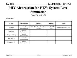
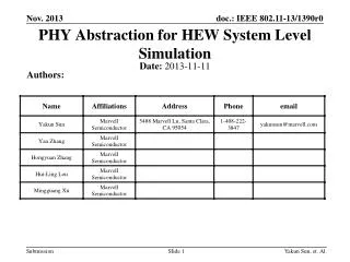
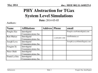
About SINR conversion for PHY Abstraction Authors: Date: 2013-11-11 Yakun Sun, et. Al.
Introduction • Effective SINR mapping is proposed for PHY abstraction [1, 2, 3]. • The effective SINR mapping, no matter what specific mapping function is adopted, operates in the same procedure. • Starting by calculating receiver-output SINR for each tone. • We discuss how to calculate receiver-output SINR. Yakun Sun, et. Al.
PHY Layer Model for System Simulation • Tx MAC layer informs PHY layer the number of bits and MCS. • Tx PHY layer does not encode anything a virtual PHY packet. • Channel includes (1) large scale fading, and (2) instantaneous channel impulse response (CIR) • Generated for performance evaluation. • Multiple virtual PHY layers may contribute to the received “signals”. • Each with a CIR. • Rx calculates channel freq response. • Rx MIMO detector only calculates SINR but does not process any signals. • Rx decoder takes SINRs across frequency tones and OFDM symbols, and predict PER for this packet. • A random number is generated and compare with PER Yakun Sun, et. Al.
Frequency Domain Received Power • Frequency domain equalization is done and the PER depends on the equalizer performance. • Frequency domain received signal power is calculated on top of the channel frequency response. • A scaling factor to compensate the guard tones. • A simple example (more factors can be added, such as cable loss…): Yakun Sun, et. Al.
Frequency Domain Received Signal Model • The (virtually) received signal at the nth tone, lthOFDM symbols is • Instantaneous channel fading is separated from the received signal power. • The power of channel frequency response |H(f)|2 is normalized, either per packet or long-term normalized. • The received noise is modeled as AWGN with variance σ2. Yakun Sun, et. Al.
SINR Calculation • Based on the receiver assumed, the equalizer output SINR can be calculated for each spatial stream. • SINR is precoding (beamforming) dependent. • Per-tone beamforming changes the effective channel fading rather than a constant/static receive signal power boost. • The beamforming method has to be aligned or specified in simulation. • SINR is receiver dependent. • Typically, linear MMSE (with or without interference whitening) or MRC for single-stream transmission is assumed. • “SINR” does not exist for ML detector, and equivalent SINR for ML has been proposed in literatures but with great computational complexity. • For example, if no interference is present (K=0), and a rank-1 transmission (x0 is a scalar). The MRC output SINR is: Yakun Sun, et. Al.
Ideal vs. Practical Channel Estimation • Receiver can assume ideal channel estimation. • Textbook SINR equations • If practical channel estimation is assumed, the impact on SINR can be represented by an additional noise for channel estimation error. • For example, a good approximation for SISO channel with one-shot channel estimation is to scale noise power by 2, (i.e., σCE2=2σ2) • Better approximations for CE errors are open to discuss. Yakun Sun, et. Al.
Comments on SINR Calculation • Given asynchronous transmission in OBSS, the transmit power and channel responses from each interfering BSS may vary (and disappear) across time. • K interfering transmitters are assumed to be frequency-selective. • To simplify the simulation, flat-fading channels can be assumed for transmitters far away (with low received power). • TxEVMcan be modeled by capping EVM-free SINR. Yakun Sun, et. Al.
Summary • Briefly introduce how the receiver-output SINR can be calculated. • Receiver-output SINR is a function of channel frequency responses and received signal power from each transmitter (desired or not). • SINR depends on the receiver type and beamforming schemes. • SINR calculation can include a simple and efficient modeling of transmitter/receiver details, such as CE error, EVM, and etc. Yakun Sun, et. Al.
References [1] IEEE 802.16m-08/004r5, Jan. 2009 [2] R1-050680, “Text Proposal: Simulation Assumptions and Evaluation for EUTRA”, 3GPP TSG RAN WG1 #41bis, June, 2005 [3] R1-061626, “LTE Downlink System Performance Evaluation Results”, 3GPP TSG RAN1 #45, May, 2006 Yakun Sun, et. Al.