Download
1 / 10
100 likes | 245 Views
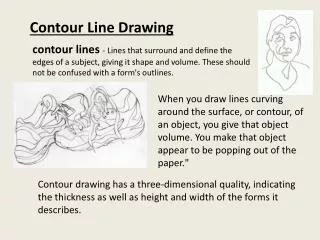
How to Incorporate a Contour Line in a Geometry. How to Incorporate a Contour Line in a Geometry. This presentation shows how to incorporate a contour line from Results in a Geometry as an Extruded 2D line in a 3D model. The technique can be used in 2D and 3D to partition modeling domains.

E N D
How to Incorporate a Contour Line in a Geometry • This presentation shows how to incorporate a contour line from Results in a Geometry as an Extruded 2D line in a 3D model. • The technique can be used in 2D and 3D to partition modeling domains. • In 3D you can use a contour line as a basis for an Extrude, Revolve, or Sweepoperation. • The particular model shown in the next few slides can be found in the Model Library of the Heat Transfer Module, under Electronics and Power Systems. However, the instructions are generic and will be applicable to any model.
Step 1: Create Surface Data Set on surface(s) of interest, choose appropriate Parameterization plane
Step 2: Create Contour plot using Surface 1 Data set, specify 1 level only, specify Contour type: Lines
Step 3: Export the Contour plot: Browse to enter a Filename, specify Data format as Sectionwise, click Export
Step 4: Add Interpolation Curve to Work Plane > Plane Geometry, specify Type: Open curve, choose Data source: File, Browse to Filename from Step 3, choose Data format: Sectionwise, specify an appropriate Relative tolerance, choose Build Selected
Step 5: Extrude the Work Plane the desired distance, choose Build Selected
Step 6: Convert to Solid: include the extruded Work Plane and the imported geometry object, choose Build All