Download
1 / 31
310 likes | 321 Views
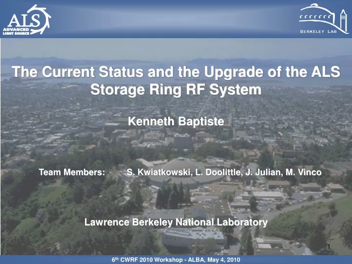
6 th CWRF 2010 Workshop - ALBA, May 4, 2010. The Current Status and the Upgrade of the ALS Storage Ring RF System. Kenneth Baptiste Team Members: S. Kwiatkowski, L. Doolittle, J. Julian, M. Vinco Lawrence Berkeley National Laboratory. 1. Outline.

E N D
6th CWRF 2010 Workshop - ALBA, May 4, 2010 The Current Status and the Upgrade of the ALS Storage Ring RF System Kenneth Baptiste Team Members: S. Kwiatkowski, L. Doolittle, J. Julian, M. Vinco Lawrence Berkeley National Laboratory 1
Outline • Overview: ALS, Booster RF (1 slide), Storage Ring RF • RF Cavity, Window Coupler, LLRF and HVPS Limits • Requirements for the Storage Ring RF Upgrade • Path/Timeline to our Current Upgrade Plan • Systems Effected by Storage Ring RF Upgrade • LLRF Description • Upgrade Schedule • Conclusion 6th CWRF 2010 Workshop - ALBA, May 4, 2010 2
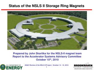
ALS Overview 6th CWRF 2010 Workshop - ALBA, May 4, 2010 3
ALS Overview 6th CWRF 2010 Workshop - ALBA, May 4, 2010 4
Booster RF HPA, IOT AI, Acrodyne Industries (commercial broadcast transmitter, modified) CPI, Communications & Power Industries (commercial broadcast IOT, K2 series, 80kW) Vb = 32.5 kV Ib = 2.6 A Gain >23 dB Eff. >65 % Po = 55 kW pk Tube #1 Failed @ 18k Hrs Htr/Cath HV Flt Tube #2 @ 5k Hrs Tube #3 On the shelf 5 6th CWRF 2010 Workshop - ALBA, May 4, 2010
Existing SR RF System ∑ 6 6th CWRF 2010 Workshop - ALBA, May 4, 2010
Existing System Layout Klystron Magic-Tee Magic-Tee Load Circulator CirculatorLoad Cav 2 & HOM Filter Cav 1 & HOM Filter 6th CWRF 2010 Workshop - ALBA, May 4, 2010 7
Existing Klystron • Philips YK-1305, 500 MHz 330kW CW • Installed 1992 • > 120,000 filament & HV hrs • 265 kW nominal, 280 kW peak • 1 Spare (not a sustainable situation • for ALS) • With the installation of ID’s, Super • Bends, increased Beam Energy & • Stored Beam, RF power demand has • steadily increased since 1992. • Gain and Efficiency are decreasing • No longer manufactured 8 6th CWRF 2010 Workshop - ALBA, May 4, 2010
Existing HVPS 56 kV @ 12 A VVT HVPS Control Cab 6th CWRF 2010 Workshop - ALBA, May 4, 2010 9
Existing Filter & Crowbar Cabinet CAP Crowbar Connections to Klystron Mod Anode 6th CWRF 2010 Workshop - ALBA, May 4, 2010 10
Existing Filter & Crowbar Cabinet CAP Mod Anode Crowbar Klystron 6th CWRF 2010 Workshop - ALBA, May 4, 2010 11
RF Cavity Limits • Manufacturer: Siemens->Accel->RI • Cavity DesignMax = 70kW • Tested to66kW@ Bldg. 27 Teststand • Currently Operates at 43kW (no beam) • Operational Limit = 55kW, No Beam • (due to the Window/coupler limitation) 6th CWRF 2010 Workshop - ALBA, May 4, 2010 12
RF Window Coupler Limits Iris Flange Profile b: 1 to 3.2 Split WR1800 Waveguide to Cavity Transition • Manufacture: Window - E2V, Waveguide - LBNL • TiN coating & test to66KWCW @ Bldg. 27 Teststand • 2 in SRRF operating at 43kW CW (no beam) • Max No Beam Power limited to 55kW • (due to cavity field heating) • Max Beam Power limited to 110kW • (due to field levels in waveguide transition) 6th CWRF 2010 Workshop - ALBA, May 4, 2010 13
SRRF Upgrade Requirements • Supply Modest Increase in Beam Power • Replace Aging Single Klystron (17 yrs) • Replace HVPS to Increase DC Power • Replace Crowbar • Replace Analog LLRF with Digital (FPGA) based system • Upgrade Controls, from ILC to PLC • Increase Diagnostic Capabilities • Increase Reliability and Maintainability 6th CWRF 2010 Workshop - ALBA, May 4, 2010 14
Beam Loading Increase Present Future Beam current (mA) 500 500 Number of Insertion Devices 11 13 Gap Positions Nom Min Nom Min Dipoles Radiation (kW) 142 142 142 142 Insertion Device Radiation (kW) 25 46 46 55 Power Loss for 3rd HC (kW) 6 9 9 9 Cavity Dissipation (x2) (kW) 43 43/50 43/50 43/53 W.G. & other losses (kW) 7 10/8 10/9 12/9 Total RF Power Reqr’d (kW) 266 293/305 293/305 304/322 Total RF Power Installed (kW) 330 330 ~400 ~400 Cav/Window Power Limit (kW) 330 330 15 6th CWRF 2010 Workshop - ALBA, May 4, 2010
Path/Timeline to the Upgrade Plan Proposal to Replace Klystron w/4 IOTs (minimal est.) 12/2005 Proposal to Replace Klystrons w/4 IOTs (revised est.) 12/2006 $2.3M Received from DOE (partial) 07/2007 Redirected to work on Top-Off Intrlk System 08/2007 European Light Source Tour (DLS, Ellettra, SLS, ALBA) 11/2007 ALS starts 500 mA Operation 08/2008 Proto-type of HV Disconnect Switch Finished 10/2008 ESLS-RF Workshop @ DLS 10/2008 Top-Off Operation Begins 02/2009 Detailed Estimate for Klystron Replacement w/4 IOTs 02/2009 $1.96M Received from DOE (final installment) 04/2009 New Beam Loading Values, IOT Reliability (ALS, DLS, Elettra) 06/2009 New Research of RF Sources, (IOT, Klystron, Solid-State) 07/2009 Revised Proposal to Upgrade SR RF System with Klystrons 08/2009 16 6th CWRF 2010 Workshop - ALBA, May 4, 2010
SRRF Upgrade Plan • Replace Single Klystron with Two TH 2161 Klystrons • Replace HV Rectifier Transformer (HVPS), increase its kVA to match the Existing VVT’s kVA rating (800 kVA) • Replace Crowbar with HV Dis-Con Sw (IGBT based) • Replace Analog LLRF with Digital system (FPGA based) • Separate Cavities, 1 cavity per klystron • Upgrade Controls, from ILC to PLC • Increase Diagnostic Capabilities • Complete Upgrade while Operating ALS on a Full User Schedule 17 6th CWRF 2010 Workshop - ALBA, May 4, 2010
SRRF Upgrade Plan 6th CWRF 2010 Workshop - ALBA, May 4, 2010 18
Klystrons Evaluated • CPI 200 kW CW …an R&D Build • Installed Sockets: None • Other Comparables • APT (LANL) 1 MW @ 700 MHz • BNL 1 MW @ 704 MHz • CESR 800 kW @ 500 MHz • HERA (DESY) 800 kW @ 500 MHz • future… ?? • Toshiba E37702 300 kW CW • …an R&D Build • Installed Sockets: None • Other Comparables • NewSUBARU 180 kW • PF @ KEK, 180 kW • VSX @ KEK, 180 kW • Thales TH 2161B 300/180 kW CW • Installed Sockets • SSRF, 3 - 300 kW, 1 – 180 kW • SLS, 1 - 180 kW • CLS, 1 - 300 kW • BSRF, 2 – 300 kW ?? • future, NSLS II?, TPS?, Pohang? Selected Order placed 3/31/2010 6th CWRF 2010 Workshop - ALBA, May 4, 2010 19
Upgraded System Layout Klystron #1 Klystron #2 Circulator #2 Circulator Load #2 Circulator #1 Cav 2 & HOM Filter Circulator Load #1 Cav 1 & HOM Filter 6th CWRF 2010 Workshop - ALBA, May 4, 2010 20
HVPS Upgrade Replaced VVT HVPS -25 kV to -50 kV @16 A LOTO Testpoints Temperature Controller (PLC & TC based) 6th CWRF 2010 Workshop - ALBA, May 4, 2010 21
HV Dis-connect Switch Plan S. Kwiatkowski: Engineer - RF Systems • Selected IGBT with < 0.1% dissipation factor • Develop & Test IGBT Stack Balance Circuit [1] & Gate Drive • Develop & Test Control Pwr Distribution to IGBT Stack • Two IGBT “Proof of Concept” Tested • Production IGBT Modules in Process • Mechanical Design of Module System in Process • System Integration with HV Dividers, Mechanical Switches • Final Testing [1] Ju Won Baek, Dong-Wook Yoo, Heung-Geun Kim. High-Voltage Switch Using Series-Connected IGBT’s with Simple Auxiliary Circuit. IEEE Transactions of Industry Applications, Vol 37, No 6 November 2001 6th CWRF 2010 Workshop - ALBA, May 4, 2010 22
IGBT, Gate Drv & Balancing Ckt. • IGBT: IXYS IXEL40N400 • 4 kV @ 40 A • < 0.1% Dissipation Factor • < $100 each to Control Pwr Distribution To/from Control Logic Passive Balancing Circuit Motorola MC33153 Gate Drive w/Desat. Protection 1 of 24 IGBT Switch Cells 6th CWRF 2010 Workshop - ALBA, May 4, 2010 23
Control Pwr Dist. & Testing “Proof of Concept” Testing Oscillator Audio Amplifier Control Pwr Distribution <1 W each 7.5 kV 3.2 kV 20k Cycle Test 6th CWRF 2010 Workshop - ALBA, May 4, 2010 24
HV Dis-Conn SW 25 6th CWRF 2010 Workshop - ALBA, May 4, 2010
Low Level RF Larry Doolittle: Engineer - Low Level RF Controls • Signal Conditioning • Onboard – driven by • packaging • Offboard – modularity, • keep close to cavity • Flexible Platform • BPM • RF Phase & Amp Monitors • Feedback Systems • Why Digital? • No drift • Perfect calibration • Can be accurately • simulated/modeled • Can add remote control & diag • Extra features are cheap, don’t • compromise reliability • Why NOT Digital? • Adds >150 ns latency, can effect • closed loop dynamics • >-150dBc/Hz added noise, ADC 6th CWRF 2010 Workshop - ALBA, May 4, 2010 26
Low Level RF • Managing Clocks & Frequencies • 1 ADC sample per FPGA clock, 65- • 130MS/s for 12-16 bit ADCs • IF near but not at center of Nyquist • zone • Higher IF RF filtering easier • 500 MHz Example • Internally generate LO & clock • 500/12 41.667 MHz IF • Mix & select lower sideband w/filter • 500*11/12 458.33 MHz LO • LO/4 114.583 MS/s clock • IF/CLK 4/11 = 0.364, Non I/Q, near • middle of Nyquist Zones (.25, .75, etc) • FPGA Features • PI Feedback (vector) • Phase calibration 6th CWRF 2010 Workshop - ALBA, May 4, 2010 27
Low Level RF • Drift Correction • Temperature stabilized passive components • Drift correction of long cable & active • components in gateware • Modulated calibration • Temporally offset for pulsed systems • Frequency offset for CW system Temperature Stabilized Keep Passive devices close to cavity (~0.5m), minimize high quality cable costs 6th CWRF 2010 Workshop - ALBA, May 4, 2010 28
Low Level RF • SLAC Interferometer Installation: • 200m optical fiber cable at S-band, no temperature stabilization • Optical signal split, converted to microwave • Two channels compared 6th CWRF 2010 Workshop - ALBA, May 4, 2010 29
Project Schedule Spring Spring Spring Spring 2010 2011 2012 2013 Order new Klystrons Test Kly’s 1 & 2 Install Kly’s 1 at a time Step I Shutdown Shutdown Shutdown Run on Existing Philips Klystron Run new Kly #1 Replace Crowbar-Filter w/HV Dis-Con Sw-Filter Step II Design, Build & Test HV Dis-Con Sw/Filter Cabinet Addition of Insertion Device(s) Modify HVPS Order new Rectifier-Transformer-Choke Test Kly 3 Step III Modify Waveguide Install new LLRF Design, Build & Test Low Level RF & Controls Run on Two new Klystrons 6th CWRF 2010 Workshop - ALBA, May 4, 2010 30
Conclusion • Upgrade Plan has Evolved • RF Cavity, Window Coupler and HVPS Infrastructure Limits OK • HV Disconnect Switch Represents Highest Risk • Long Path to Upgrade Plan • Challenging to Meet Three 5-7 week Installation Shutdowns 6th CWRF 2010 Workshop - ALBA, May 4, 2010 31