Download
1 / 39
390 likes | 526 Views
C-BAND ACCELERATION ACHIEVEMENTS, USE AND APPLICATION. D. Alesini (LNF-INFN, Frascati (Italy)). THANKS TO ALL CONTRIBUTORS. Design : V. Spizzo (Univ. of Rome “La Sapienza ”) Mechanical design and Realization : V. Lollo , R. Di Raddo , P. Chimenti. Test at KEK :

E N D
C-BAND ACCELERATION ACHIEVEMENTS, USE AND APPLICATION D. Alesini (LNF-INFN, Frascati (Italy))
THANKS TO ALL CONTRIBUTORS Design: V. Spizzo (Univ. of Rome “La Sapienza”) Mechanical design and Realization: V. Lollo, R. Di Raddo, P. Chimenti Test at KEK: L. Palumbo, R. Boni, A. Gallo, S. Quaglia, F. Marcellini, A. Battisti, G. Di Pirro, R. Clementi Toshiyasu Higo, Shuji Matsumoto, K. Kakihara (KEK) Silvia Verdu Andres (CERN)-BDR Klystron, Modulator, Installation, logistics, financial support: R. Boni, M. Bellaveglia, G. Di Pirro, A. Gallo, R. Clementi Tuning: G. Campogiani, A. Mostacci, S. Persichelli, R. Zennaro, A. Citterio Beam dynamics: M. Ferrario, V. Fusco, C. Vaccarezza SLED design: B. Spataro, F. Marcellini Analysis of cut prototype structure: S. Bini, V. Lollo, A. Battisti, C. Federici TIARA project management: M. Biagini • Multi-bunch beam dunamics: M. Migliorati, A. Mostacci, C. Vaccarezza, S. Tocci • A. Grudiev, G. Riddone
OUTLINE • - C-Band accelerating structures for SPARC (e- acc. TW single bunch) • C-Band structures for multi-bunch RF LINACS: ELI_NP proposal • (e- acc. TW multi bunch) • - C-Band structures for hadrontherapy (SW ions) (few slides) • PSI • SPRING-8
SPARC_LAB (Sources for Plasma Accelerators and Radiation Compton with Lasers And Beams) Multi-purpose radiation/acceleration laboratory at LNF-INFN Experimental beam lines for FEL, Laser plasma acceleration, THz radiation, Compton source,… Photo-injector
SPARC PHOTO-INJECTOR RF GUN: -2.856 GHz -1.6 cell Solenoids LINAC: -S BAND -3 sections (3 m long) -Diagnostics (RF deflector) -quadrupoles matching -seeding UNDULATORS SPARC
ACC. SECTION GUN SPARC ENERGY UPGRADE WITH C BAND SYSTEM: MOTIVATION The SPARC energy will be upgraded from 170 to >240 MeV by replacing a low gradient S-band traveling wave section with two C-band units. We decided to implement this system at SPARC to explore the C Band acceleration (RF components, construction at LNF TW sections, SLED, syncronization) in hybrid scheme with S Band: -Higher gradients -Very promising from the beam dynamics point of view Klystron N°1 3 dB splitter ATT E ≈ 170 MeV 20 ÷ 22 MV/m ≈ 130 MeV ACC. SECTION ACC. SECTION PULSE COMPRESSOR ≈ 13 MV/m Klystron N°2 C-band acc. structures > 35 MV/m • The new C-band system consists mainly of: • 2 accelerating sections (1.4 m long) • 1 C-band klystron (50 MW), by Toshiba Ltd (JP) • 1 Pulsed HV modulator supplied by ScandiNova (S) • WR187 waveguide system • 400 W solid state driver supplied by MitecTelecom (CDN) • SLED E > 240 MeV 1.4 m 1.4 m ≈ 50 MW ≈ 50 MW C-band Station 2.5 μs ≈ 100 MW/0.20μs 5712 MHz – 50 MW C-band ENERGY COMPRESSOR
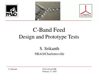
Design of C Band TW structures for SPARC (D. Alesini, et al, SPARC Note RF-11/002, 01/02/11) PRF_OUT Structure design (CI) The structure has been designed in order to: -simplify the fabrication (Constant Impedance) -reduce the peaksurface fieldon the irises when the structure is feed by the SLED pulse (large irises-Constant Impedance) -obtain an average accelerating field >35 MV/m with the available power from the klystron; -reduce the unbalance between the accelerating field at the entrance and at the end of the structure, due to the combination of power dissipation along the structure and SLED pulse profile (Constant Impedance). -reduce the filling time of the structure to input pulse length and, consequently, to reduce to the BDR (large irises) -increase the pumping speed (large irises) PRF_OUT PRF_IN Coupler design Based on the “new generation” of couplers for high gradient operation proposed at SLAC for high gradient X Band structures (waveguide couplers)
ACCELERATING STRUCTURE OPTIMIZATION The dimensions of the single cell have been optimized to simultaneously obtain: -lowest peak surface electric field on the irises with the SLED input pulse; -an average accelerating field of, at least, 35 MV/m with the available power from the klystron; -the largest iris aperture for better pumping, reduced wakefields contribution and reduced filling time of the structure (related to the breakdown rate probability). Safety value at least in X Band Reduction of the Attenuation Reduction of the magnetic field (pulsed heating) Elliptical shape
REALIZATION OF THE PROTOTYPE (@LNF+Local firm (COMEB)) Cooling pipes Cells Turning machine Cell Ra<0.05m tolerances 2m Tuning by deformation Input coupler cumputer controlled milling machine Ra<0.2m tolerances 20m Output coupler: Electro discharge machining Ra<1m tolerances 20m
REALIZATION OF THE PROTOTYPE (@LNF+Local firm (COMEB)) • The structure has been brazed @ LNF in several steps: • -Cells • Couplers • Final brazing • Intermediate RF measurements have been done during realization Main problem during the realization: -alignment of coupler and cells in the final brazing process
Test at high power (KEK) of the prototype: the setup The input power was monitored by the directional coupler located between SKIP and the accelerator structure. The transmitted power was monitored in front of each RF load. The currents emitted from the accelerator structure were monitored in both directions. Pipes with an inner diameter of 40 mm were connected from the beam ports of the accelerator structure with ceramic insulation in front of the Faraday cups. Acoustic sensors were mounted on the test structure and various parts of the waveguide. These were pressed against the surfaces by using fasteners.
HIGH POWER TEST: Processing History The high-power test started on November 5 and was completed on December 13, 2010. For almost one month of processing, from November 5 until December 2, more than 108 RF pulses of 200 ns width were sent into the structure with a repetition rate of 50 Hz. For a couple of days the RF pulse length was changed to 300 ns and for one day (November 12) the repetition rate was decreased to 25 Hz. On November 15, SKIP was switched on.
Tuning of the prototype (in coll. with Univ. La Sapienza) Structure under tuning Tuning results The technique we used has been derived from a well know technique (J. Shi, et al., proc. of LINAC 08, 2008). Only imaginary parts of the local reflection coefficient can be compensated. A residual real part (irises?) cannot be compensated. A strong detuning of the coupler has been found.
PROTOTYPE INTERNAL INSPECTION C1 I1 I2 O1 O2 O3 I3 C12
INPUT COUPLER INSPECTION I2 A Reflective, macro-crystals, Clean, not signs of discharges or damages Opaque, not reflective, presence of oxidation, Colored part, what happened? Contamination? (SEM micro-analysis in progress…) Side B I2 B I2 B Side A I2
CENTRAL CELLS -For all cells no visible pits or signs of discharges -Presence of macro-crystals -The cells are perfectly reflective, no oxidation
SEM IMAGES OF PITS IN 1st ACCELERATING CELL S. Bini, V. Lollo
Status of final C-band acceleratingstructures See M. Biaginipresentation
C-BAND STRUCTURES FOR MULTI-BUNCH RF LINACS: ELI_NP PROPOSAL In the context of the ELI-NP ResearchInfrastructure, to be builtatMagurele (Bucharest, Romania), an advanced Source of Gamma-rayphotonsisplanned, capable to produce beams of mono-chromatic and high spectraldensity gamma photons. The Gamma Beam System isbased on a Compton back-scattering source. Itsmainspecifications are: photonenergytunable in the range 1-20 MeV, rmsbandwidthsmallerthan 0.3% and spectraldensity lager than 104photons/sec.eV, with source spot sizessmallerthan 100 microns and linear polarization of the gamma-raybeamlargerthan 95%. 14 C-band cavities 1.5 m long
MULTI-BUNCH EFFECT ANALISYS • Cumulative beam break-up in LINACS: general considerations • Cumulative beam break-up in the ELI-NP C-Band LINAC • C-Band Damped structures • Multi-bunch effects in energy modulation along the train: Beam loading and its compensation TRANSVERSE EFFECTS LONGITUDINAL EFFECTS
beam breakup in LINACS: general description Beam trajectory Any beam offset or structure misalignment can excite transverse long range wakefield which will then cause subsequent bunches to be deflected. The dipole mode TM11-like gives, generally the dominant effect in LINACS. LINAC axis VT Off-axis beam trajectories arise due to a variety of errors: -Offset at injection -Misalignment of focusing magnets -Misalignment of accelerating sections Bunch distance (or s) B field of the TM11-like mode Leading bunch Trailing bunch
Beam breakup analysis: trackingcode -Analytical approaches can be used to evaluate the beam breakup effects (for example Mosnier theory). -Tracking codes Eacc=average accelerating field Injector S-band Ideal axis Einj=beam energy after injector Booster LINAC (C-band) Beam injection conditions at the entrance of the linac booster (yIN,y’IN) Beam output positions (yOUT,y’OUT) Phase space @ LINAC exit y’OUT 1st bunch of the train Other bunches yOUT Equivalent beam emittance increase
Tracking results • Hypothesis: • Initial condition at linac injection equal for all bunches • Constant -function • Perfect build-up mechanism of all transverse wakes that decays with the quality factor of the mode • One single mode trapped in each cell • Maximum transverse kick sampled by each bunch
Mitigation of multi-bunch effect with damped structures DAMPED STRUCTURES C-band non damped SPARC energy upgrade
RF linacs with damping of dipole modes Dipoles modes propagate in the waveguide and dissipate into a load CLIC structures X-band, high gradient C-Band structures Spring-8 • Advantages • 1. Strong damping of all modes above waveguide cut-off • 2. Possibility of tuning the cells • 3. Good cooling possibility • Disadvantages • Machining: need a 3D milling machine • Multipole field components (octupole) but not critical at least for CLIC • Advantages • Easy machining of cells (turning) • 2D geometry: no multipole field components • Disadvantages • 1. Critical e.m. design: notch filter can reflect also other modes. • 2. Not possible to tune the structure • 4. Cooling at 100 Hz, long pulse length (?)
ELI Damped structure TW cells Input coupler Output coupler
ELI Damped structure: effect of waveguide damping w=13 mm w w=7 mm Q<100 First dipole mode (TM11-like) passband HFSS
ELI Damped structure: Mechanical drawings, realization and prototype • The fabrication of a prototype with a reduced number of cells is necessary to: • Test the effectiveness of the dipole mode damping including the test the absorbing material performances • Test the vacuum properties of the structure with absorbing material • Perform the low power tests and the tuning of the structure • Test the high gradient performances of the structure
OUTLINE: MULTI-BUNCH EFFECTS • Cumulative beam break-up in LINACS: general considerations • Cumulative beam break-up in the ELI-NP C-Band LINAC • C-Band Damped structures • S-Band Injector beam break-up • Multi-bunch effects in energy modulation along the train: Beam loading and its compensation TRANSVERSE EFFECTS LONGITUDINAL EFFECTS
Beam loading: loaded accelerating field Ez_unloaded (seen by 1st bunch) Ez 1st bunch passage Ez_loaded (after1st bunch passage) L 0 z Ez 2nd bunch passage Ez_unloaded Ez_loaded (seen by 2nd bunch) L z 0 vg*T (T bunch spacing=15 ns)
Beam loading: build-up Ez Ez_unloaded Ez_loaded (steady state) L 0 z
Beam loading: possible compensation Pre-pulse to fill the structure Beam loading compensation during transient Injection of the first bunch of the train Beam loading compensation after one filling time of the structure
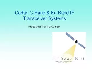
C-BAND structures for Handron therapy Courtesy from Silvia Verdú-Andrés TERA Foundation, Novara, Italy and Instituto de Física Corpuscular IFIC (CSIC-UV), Paterna (Valencia), Spain
Accelerators for Hadrontherapy: Cyclinac The Italian research foundation TERA proposes a new type of accelerator, the cyclinac, made of a high-frequency linac which boosts the energy of the hadrons accelerated by a cyclotron. CELL COUPLED LINAC • Cell Coupled Linac • Standing-wave structure • RF frequency: 5.7 GHz • 2.5 ms-long pulse at 300 Hz CABOTO (CArbon BOoster for Therapy in Oncology)
Main cyclinacfeatures • Active energy modulation: No absorbers are needed to degrade the beam energy. The linac is divided in different sections, called units, each one fed by its own klystron. Beam energy modulation is done by switching on and off the different units in which the linac is divided and “fine” energy modulation is obtained by acting on the power (amplitude and phase) used to feed the last active unit. . • CABOTO (Carbon BOoster for Therapy in Oncology ) is the newest proposal of TERA and will accelerate C^{6+} and H_2^{+} from 150 up to 400 MeV/u. It works at 5,7 GHz. The CCL (Cell Coupled Linac) is made of eighteen 1,3 m long units .
CONCLUSIONS C-Band accelerating structures have been proposed for the SPARC photoinjector energy upgrade; A prototype with a reduced number of cells has designed, fabricated and tested at high power (KEK) giving excellent results in term of BDR @ 50 MV/m The final accelerating structures are in fabrication in parallel with the test and installation of the high power system The multi-bunch operation with C-band cavities has been carefully studied in the framework of the ELI_NP proposal and damped C-band structures are under development One of the possible applications of C-band cavities for proton/carbon acceleration has been illustrated