Download
1 / 38
570 likes | 836 Views
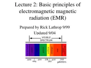
electromagnetic and magnetic circuit principles. voltage and current waveforms. Example. When an instantaneous voltage of 500 Sin (314t + π/4) is applied to a series circuit of R and L, the current is found to be 10Sin (314t - π/6). Calculate:

E N D
Example When an instantaneous voltage of 500 Sin (314t + π/4) is applied to a series circuit of R and L, the current is found to be 10Sin (314t - π/6). Calculate: i) Peak voltage ii) Frequency iii) Phase angle iv) Impedance v) Resistance vi) Inductance
Example • Peak voltage = 500v • Frequency f = 314/2π = 50 Hz. • Phase angle π/4 + π/6 = 45o + 30o = 75o • Impedance Z = V/I = 500/10 = 50 Ω
Example • Resistance = Z Cos φ = 50 x 0.2588 = 12.94 Ω • Inductive reactance - XL= Z Sin φ = 50 x 0.9659 = 48.30Ω • Inductance L = XL/ 2πf = 48.30/2π x 50 • = 0.1537 H
Circuit possessing resistance only instantaneous value of voltage and current v = VmsinӨ and i = Vm/R sinӨ i = ImsinӨ = Imsinπ2Өft
Circuit possessing inductance only: instantaneous value of induced e.m.f.: e = -L.di/dt = 2πfLIm instantaneous value of applied voltage v = 2πfLIm cos 2πft = 2πfLImsin(2πft+π/2)
phasor diagram for the inductive circuit VL leads by 90o VL VR
Inductive reactance Vrms/Irms= 0.707Vm/0.707Im = 2πfL = inductive reactance [XL] I = V/2πfL = V/XL[ohms]
Example • An inductor of 0.6H and negligible resistance is connected across a 120 V a.c. supply. • Calculate the current when the frequency is: • i) 30 Hz • ii) 200 Hz
Example • i) XL= 2πfL = 2π x 30 x 0.6 = 113 Ω • IL= V / XL= 120 / 113 = 1.06 A • ii) XL = 2πfL = 2π x 200 x 0.6 = 753 Ω • IL= V / XL= 120 / 753 = 0.159 A
Circuit possessing capacitance only v = Vmsin θ = Vmsin 2πft i = C dv/dt i = 2πfCVm cos 2πft = 2πfCVmsin(2πft+π/2)
phasor diagram for the capacitive circuit VR VC lags by 90o VC
Capacitive reactance Vrms/Irms= 0.707Vm/0.707Im = 1/(2πfC) = capacitive reactance [XL]
Example • A capacitor of 0.6 μF is connected across a 120 V ac supply. Calculate the current when the frequency is: • i)30Hz • ii) 200 Hz
i) XC= 1 / 2πfC = 1 / 2π x 30 x 0.6 x 10-6 = 8842 Ω • IC= V / XC= 120 / 8842 = 13.6 mA • i) XC= 1 / 2πfC = 1 / 2π x 200 x 0.6 x 10-6 = 1326 Ω • IC= V / XC = 120 / 1326 = 0.09 A
Series Resonance • The resonance of a series RLC circuit occurs when the inductive and capacitive reactances are equal in magnitude but cancel each other because they are 180 degrees apart in phase. The sharp minimum in impedance which occurs is useful in tuning applications. The sharpness of the minimum depends on the value of R and is characterized by the "Q" of the circuit.
Series Circuits (R,L,C) impedance [Z] =√{R2 +(XL -XC)2} φ = phase angle = tan-1(XL-XC)/R), Cos-1 R/Z, Sin-1 = (XL - XC) / Z phasor diagram
Example • A 10 Ω resistor and 150μF capacitor are connected in series across a 200 Hz, 200 V ac supply. Calculate: • i) Circuit impedance • ii) Current • iii) Phase angle
Example i) Circuit impedance. XC= 1 / 2πfC = 1 / 2π x 200 x 150 x 10-6 = 5.305 Ω Z = √ R2 + XC2 = √ 102 + 5.3052 = √128.143 = 11.32 Ω ii) Current = I = V/Z = 200 / 11.32 = 17.67 A iii) Phase angle = tan-1 XC / R = 27.95 degrees leading
Series Resonance (R,L,C) XL =1/XC f = 1/{2π√(LC)} phasor diagram definition: acceptor circuit graph of current and impedance plotted against Z
Q factor (at resonance) Q = XL/R = 1/R √(L/C) bandwidth - (f2-f1) - definition of half-power points Q = fr/(f2-f1)
Parallel Circuits (R,L,C) supply current = √V/R + V/XL+ XCV) φ = phase angle = phase difference VSand IS φ = tan-1 (IL - IC)/IR phasor diagram
Parallel Resonance (R,L,C) f = 1/(2πL) √(L/C - R2) phasor diagram definition: rejector circuit dynamic impedance RD= L/CR Q factor (at resonance) = XL/R
Terms • Resistance is the opposition to current flow by a resistor • Reactance, is similar, it is the interference of a capacitor or an Inductor to current flow • XL is inductive reactance and XC is capacitive reactance • Impedance (Z) is actually the overall opposition to current presented by the circuit
Conductance, Susceptance, and Admittance are the opposites to Resistance, reactance and impedance
Impedance triangle Impedance Z Reactance X Resistance R
Admittance triangle Conductance G Susceptance B Admittance Y
Conductance [G] = R/Z2. Is 1/R when X is = 0 • admittance [Y] = 1/Z = R/Z2 • susceptance [B] = X/Z2. Is 1/X when X is = 0 • Y = G+ jB and tanφ = B/G
R and L in series Z = R +jXL= Z < φ admittance = Y = 1/Z = (R/Z2 - jXL/Z2) = G – jBL = Y < -φ
R and C in series • Z = R -jXC= Z<-φ • admittance = Y = 1/Z = (R/Z2 + jXC/Z2) = G + jBC = Y<φ