Download
1 / 38
380 likes | 516 Views
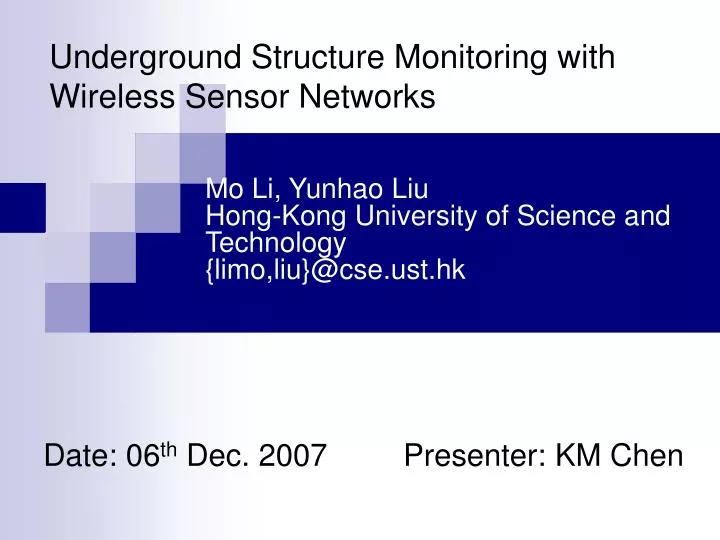
Underground Structure Monitoring with Wireless Sensor Networks. Mo Li, Yunhao Liu Hong-Kong University of Science and Technology {limo,liu}@cse.ust.hk. Date: 06 th Dec. 2007 Presenter: KM Chen. Outline. Motivation Overview of Structure-Aware Self-Adaptive sensor system (SASA)

E N D
Underground Structure Monitoring with Wireless Sensor Networks Mo Li, Yunhao Liu Hong-Kong University of Science and Technology {limo,liu}@cse.ust.hk Date: 06th Dec. 2007 Presenter: KM Chen
Outline • Motivation • Overview of Structure-Aware Self-Adaptive sensor system (SASA) • Detecting and locating the collapse hole • Accident reporting • Displaced node detection and reconfiguration • Hardware • Application Scenario • Experiment and Performance • Simulation • Related Work • Conclusion
Motivation • Over the last decade, collapses account for more than 50% of fatalities in U.S. in coal mine • The unstable nature of geological construction in coal mines makes underground tunnels prone to structure changes. • Environment monitoring in underground tunnels had been a crucial task to ensure safe working conditions in coal mines. • There is a need to develop a wireless sensor network system to quickly detect the collapse hole regions and accurately provide location references to evacuate workers from the dangerous zone.
Outline • Motivation • Overview of Structure-Aware Self-Adaptive sensor system (SASA) • Detecting and locating the collapse hole • Accident reporting • Displaced node detection and reconfiguration • Hardware • Application Scenario • Experiment and Performance • Simulation • Related Work • Conclusion
Design of SASA (1/3) a) Stationary sensor nodes are deployed on the walls and ceiling of tunnels to form a mesh network.
Design of SASA (2/3) b) - Unfold 2 walls of the tunnel and builds a 2-D representation of the 3-D deployment on the inner surface of the tunnel. - Nodes are configured with 2-D coordinates on the unfolded 2-D surface then transformed into the 3-D corresponding locations with the knowledge of longitudinal section.
Design of SASA (3/3) c) - The distance between 2 nodes in the 3-D real environment is less than or equal to the distance between the pair in the unfolded 2-D view. - The real connectivity of the sensor network is no less than shown in the 2-D representation.
Definitions and Theorem • Edge node: A node defines itself as an edge node if the 2 adjacent neighbor nodes are detected lost during a time period. • Hole Polygon: The largest polygon outlined by the collapsed sensor nodes with every edge ending at 2 adjacent nodes. • Theorem: The convex hull of edge nodes in SASA encloses the hole polygon. Convex Hull Hole Polygon Edge node (2 adjacent neighbors are detected lost)
Detecting and locating the collapse hole • Goal: Let sensor nodes to maintain a set of their neighbors. When nodes detect a loss of neighbors, a hole is detected. Collapse hole
Detecting and locating the collapse hole Question: How to maintain a neighboring set? Node Beaconing Mechanism • Each node maintains a neighboring nodes list in memory. • Each node periodically broadcasts beacon messages that include its location. • Upon receiving a beacon message, the node updates the corresponding entry. • If a node fails to update an entry in a fixed time interval, then it represents the loss of the neighbor
Detecting and locating the collapse hole Problem: • It was observed that the neighbor set of a node is highly unstable, even if all the nodes work normally. Solution: • SASA deploys sensor nodes in a cellular hexagonal placement such that the node distribution is uniform. • Every pair of adjacent nodes are separated by the same interval . • Each node is limited to maintain a neighbor set to the 6 adjacent nodes.
Detecting and locating the collapse hole • How to define a hole detection? • Only failure of at least 2 adjacent nodes are necessary to define an edge node. Nevertheless, if 2 adjacent nodes fail simultaneously, a hole is detected • What about single node failure? • Unfortunately a small hole affecting only 1 sensor node can not be detected.
Accident reporting Goal: When edge nodes detect a hole, they report to the sink with the locations so that the hole can be illustrated by calculating the convex hull. Problem: • Create traffic peak and increase collision domain. Solution: Randomized Forward Latency and Data Aggregation • Insert a flag into the beacon messages, which indicates whether the beaconing node is an edge node. • Upon receiving other edge nodes’ beacon message, an edge node records them locally. • When this edge node sends out its report message, it aggregates all the recorded locations of its nearby edge nodes. • If an edge node receives a report message containing its own location, it simply forward this message instead of creating a new one. • The sink will send out reply to limit the number of retransmission.
Displaced node detection and reconfiguration Goal: Rapidly detect displaced nodes and reconfigure with correct locations in order to maintain system validity. Centralized approach • When the sink receives report messages with the edge nodes locations and approximate the hole region, it broadcasts the convex hull area. • Every node within the convex hull will start detecting its surroundings and check its location from beacon message. • If the 2 locations differ beyond some threshold, then it knows it’s being displaced.
Displaced node detection and reconfiguration Distributed approach • There are 3 types of edge nodes: • Edge nodes that lose neighbors but themselves do not move • Since their locations are correct, they don’t need to be reconfigured • Edge nodes that fall into an area where no normal node exists • They have no impact on normal nodes, they do not need to be reconfigured either. • Edge nodes that fall into other normal node range • Stop beaconing . This operation will lead the neighboring displaced nodes to become edge nodes, if they are not yet.
Displaced node detection and reconfiguration • Centralized approach Advantage: Short latency when the hole is closer to the sink • Disadvantage: May suffer long latency and low accuracy due to high link loss rate in coal mine, especially when a collapse area in a long tunnel is far from the sink. Distributed approach Advantage and disadvantage: Independent of the distance to the sink. In summary: • Combining both algorithms provides efficient and reliable for various situations • Turn them off or reconfigure their locations to conform to their new positions.
Displaced node detection and reconfiguration Location Calculation: • Suppose A and B drop into a new area surrounded by 3 resident nodes. • When A first detect the surrounding 4 nodes, it calculates a new location as (32.5, 19.25) and replaces the original locations. • When B detects its surroundings, it utilizes the new location of A and calculate a new location as (15.63, 11.56). • When A iteratively calculates its new location, it will get a more accurate result of (11.41, 7.14)
Displaced node detection and reconfiguration (10, 17) A (100, 100) A (32.5, 29.25) A (11.41, 7.14) (20, 0) (0, 0) B (100, 120) B (15.63, 11.56)
Outline • Motivation • Overview of Structure-Aware Self-Adaptive sensor system (SASA) • Detecting and locating the collapse hole • Accident reporting • Displaced node detection and reconfiguration • Hardware • Application Scenario • Experiment and Performance • Simulation • Related Work • Conclusion
Hardware • Mica2 platform developed at UC Berkeley • The MPR400 radio board employed has a 7.3 MHz microprocessor. • 128K bytes of program flash memory. • 512K bytes of measurement flash memory. • 868/916 MHz tunable chipcon CC1000 multi-channel transceiver with a 38.4 kbps transmitting rate is employed for wireless communication with a 500 foot outdoor range
Outline • Motivation • Overview of Structure-Aware Self-Adaptive sensor system (SASA) • Detecting and locating the collapse hole • Accident reporting • Displaced node detection and reconfiguration • Hardware • Application Scenario • Experiment and Performance • Simulation • Related Work • Conclusion
Application Scenario • Cooperate with S.H. Coal Corporation and selected the D.L. coal mine as the experimental environment. • D.L. coal mine is the is one of the mist automated coal mines, yielding the second largest production of coal worldwide. • Slightly sloped 14-kilometer long main tunnel from the entrance above the ground surface and goes 200 meter deep underground.
Application Scenario Requirements for SASA implementation in D.L. coal mine Remote management: Remotely maintain and manage the entire monitoring system, efficient and robust communications and routing mechanisms are required under all conditions. In-Situ interactions: Besides stationary sensors deployed on the walls, poles and floors, miners carry mobiles sensors providing real-time geographical references. Awareness of structure variations: Using node collaborating mechanism for collapse detection. Maintenance of system validity: Maintaining the validity of the monitoring system in extreme situation.
Outline • Motivation • Overview of Structure-Aware Self-Adaptive sensor system (SASA) • Detecting and locating the collapse hole • Accident reporting • Displaced node detection and reconfiguration • Hardware • Application Scenario • Experiment and Performance • Simulation • Related Work • Conclusion
Experiment and Performance • A prototype system with 27 Mica2 motes is implemented in the D.L. coal mine. • It is distributed on a tunnel wall about 12 meters wide and 5 meters high. • Nodes are pre-configured with their location coordinates. • Nodes are placed in hexagonal mesh regulation
Experiment and Performance • Hole detection percentage: A hole is counted as undetected if less than 3 nodes reports are received by the sink. • Hole detection error: The error in distance between the real and detected position of the hole region. • Reconfiguration error (2-D or 3-D): Localization error in the reconfiguration process.
Experiment and Performance • Over 80% of the detected holes are located within 1 meter from its real position and 99+% are less than 2 meters. • All the 2-D reconfiguration errors and over 80% of the 3-D reconfiguration errors are below 3 meters
Experiment and Performance • Detection latency: Time from when the hole emerges until it is detected • Turn-off latency: The latency when the displaced nodes were turned off. • Reconfig latency: Latency when reconfiguring the displaced nodes according to the normal nodes surrounding them. • Short beacon interval leads to short latency. However, frequent beaconing brings large overhead, heavy collisions and increased packet loss
Experiment and Performance • The packet loss rate rapidly drops as the beacon interval increases while under short beacon intervals (0.8s), then becomes stable around a fixed level. • The loss rate is heightened as the exerted traffic overhead increases.
Experiment and Performance • Observations: • We can carefully select a proper beacon interval for a specific application workload to balance communication quality and the processing latency • Shorter beacon interval to reduce the processing latency if the application workload is light. • Longer beacon interval to reduce the packet loss rate if the application workload is heavy.
Outline • Motivation • Overview of Structure-Aware Self-Adaptive sensor system (SASA) • Detecting and locating the collapse hole • Accident reporting • Displaced node detection and reconfiguration • Hardware • Application Scenario • Experiment and Performance • Simulation • Related Work • Conclusion
Simulation • 2000 nodes were simulated on a 1000m x 20m plane. • Nodes were placed in a hexagonal mesh regulation with 3 meter interval between each node. • A transmitting rate of 16 packet/s is used in the simulation for the nodes’ communication channels.
Simulation • Detection error is stable as slightly decreases as the hole size increases. • Larger hole includes more edge nodes, giving a more accurate outline of the hole region. • When the hole size increases, the outline of the edge nodes becomes tighter therefore the precision is dramatically increased.
Simulation • When the hole is close to the sink, the centralized algorithm benefits from rapid information collection and reaction from the sink. • When the hole is far away from the sink, centralized algorithm suffers from the round-trip time from the sink. The distributed algorithm is not affected. • As the packet loss rate between any 2 communicating nodes, and the random node failure rate increase, the misreport ratio also increases. • Need to decrease the beacon frequency in order to preserve a better communication channel.
Outline • Motivation • Overview of Structure-Aware Self-Adaptive sensor system (SASA) • Detecting and locating the collapse hole • Accident reporting • Displaced node detection and reconfiguration • Hardware • Application Scenario • Experiment and Performance • Simulation • Related Work • Conclusion
Related Work • Wireless sensor networks for habitat monitoring [A. Mainwaring, J. Polastre, R. Szewczyk, D. Culler and J. Anderson] • A Wireless Sensor Network for Structural Monitoring [N. Xu, S. Rangwala, K. K. Chintalapudi, D. Ganesan, A. Broad ] • Hole problem in wireless sensor network [N. Amed, S. S. Kanhere and S. Jha] • Coverage hole • Routing hole • Jamming hole • Sink/black/worm holes
Outline • Motivation • Overview of Structure-Aware Self-Adaptive sensor system (SASA) • Detecting and locating the collapse hole • Accident reporting • Displaced node detection and reconfiguration • Hardware • Application Scenario • Experiment and Performance • Simulation • Related Work • Conclusion
Summary and Future Work • By regulating the mesh sensor network deployment and formulating a collaborative mechanism based on the regular beacon strategy, SASA is able to rapidly detect structural variations caused by underground collapses • The collapse holes can be located and outlined, and the detection accuracy is bounded. We also provide a set of mechanisms to discover the relocated sensor nodes in the hole region. • How to organize mobile nodes to form efficient collaborative groups is a challenging issue. • Single hole detection.